



A capacitive load needs both a running-power check and a startup check. During startup, the source must supply the equipment current and the current charging its input capacitors. A supply that carries the steady load may still enter protection before the rail reaches its operating voltage. For an OEM design, approve the exact source, downstream protection, load capacitance, and startup sequence together.
This is an output-side DC charging problem. The separate guide to AC input inrush when starting multiple power supplies addresses a different current path. Passing that input-side check does not establish that downstream electronics will start.
Article sections
Define the capacitance the source actually sees
Record the capacitors connected when power first arrives, including input filters, controller modules, and added energy-storage boards. Identify capacitance behind each controlled switch separately. A branch connected later presents a different event from the same branch present before the source starts.
In its application note on large capacitive loads, Texas Instruments shows how capacitor charging can interact with protection and the thermal limits of a series power switch. The component examples establish a mechanism, not an allowable capacitance for a WEHO supply. Ask for the exact source and switch restrictions rather than transferring another design’s values.
Calculate the charging demand with a stated ramp
For a capacitor with approximately constant capacitance and a linear voltage rise, use IC = C × ΔV / Δt. Texas Instruments explains this relationship in its discussion of capacitor charging and controlled rise time. Add the other current drawn during that same interval. A shorter requested rise time raises the charging demand.
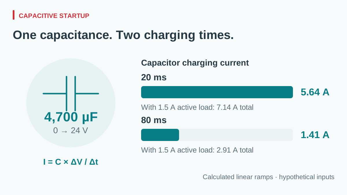
Consider a hypothetical 24 V control branch with 4,700 µF connected at startup. Assume its other electronics draw a constant 1.50 A throughout the ramp, the capacitor initially has 0 V, and no other source contributes current. These assumptions are for calculation; equipment whose electronics turn on at a threshold needs its actual changing current profile.
| Assumed startup case | Capacitor current | Total source current during the ramp |
|---|---|---|
| 4,700 µF, 0 to 24 V in 20 ms | 0.0047 × 24 ÷ 0.020 = 5.64 A | 5.64 + 1.50 = 7.14 A |
| 4,700 µF, 0 to 24 V in 80 ms | 0.0047 × 24 ÷ 0.080 = 1.41 A | 1.41 + 1.50 = 2.91 A |
| 5,640 µF, 0 to 24 V in 40 ms | 0.00564 × 24 ÷ 0.040 = 3.384 A | 3.384 + 1.50 = 4.884 A |
View full diagram ↗
The last row assumes a project-specific +20% capacitance tolerance. It does not impose that tolerance on every capacitor. At nominal capacitance, stored energy at 24 V is E = ½CV² = 0.5 × 0.0047 × 24² = 1.3536 J. The longer ramp reduces current; it does not eliminate the energy that must be delivered.
These figures are a demand estimate, not a prediction of a supply’s startup waveform. They omit wiring impedance, capacitor ESR, current-limit dynamics, voltage-dependent capacitance, and the switching behavior of the load. Use minimum and maximum effective capacitance from the actual component information when those effects matter.
Choose the change that addresses the observed limit
First establish which device interrupts startup. A source entering current limit, an electronic fuse reaching its timer limit, and a controller repeatedly crossing undervoltage lockout can produce similar equipment symptoms. Keep source-terminal voltage, load-terminal voltage, and the relevant status signal time-aligned with branch current.
A slower controlled ramp may reduce charging current, but the load must tolerate the longer startup. A series charging device must also withstand the resulting voltage, current, duration, and repetition. TI’s large-capacitance note illustrates why switch heating can constrain startup even when the selected charging current appears reasonable.
Sequencing branches can reduce coincident demand when the equipment permits it. A precharge arrangement may be another design option, with its bypass state and repeated-start behavior verified. Simply fitting a larger source leaves these interface questions unanswered. Increasing capacitance to improve another symptom also creates a new startup configuration that needs checking.
Write a startup acceptance matrix
Agree on measurable criteria before trying samples. For illustration, a project might require the load node to reach 22.8 V within 100 ms and remain between 22.8 V and 25.2 V afterward. Those are hypothetical equipment requirements, not WEHO ratings or universal 24 V limits. The controller’s own permitted ramp and reset sequence remain separate requirements.
| Condition to record | Why it changes the test | Evidence to retain |
|---|---|---|
| Source input and ambient | Startup capability may differ across the documented operating envelope. | Measured input, local ambient, mounting, and exact revision. |
| Capacitance and initial voltage | A fully discharged start differs from a rapid restart with retained charge. | Parts list, effective capacitance range, and measured pre-start voltage. |
| Enabled branches and timing | Active load current may change while the rail rises. | Control sequence and time-correlated current record. |
| Protection and recovery state | A successful eventual start can conceal repeated interruptions. | Source and protection status, time to stable operation, and equipment reset record. |
| Repeated starts | The allowed repetition depends on component and system thermal limits. | Agreed interval, number of events, and observed deviations. |
Keysight’s startup validation overview describes controlling the input and load while capturing output behavior. Apply that principle to the complete branch: keep the fixture unchanged when comparing candidates, then repeat the agreed cases in the actual equipment configuration. A startup test at one convenient input and room temperature answers only that case.
Review an NDR-240-24 candidate against the startup record
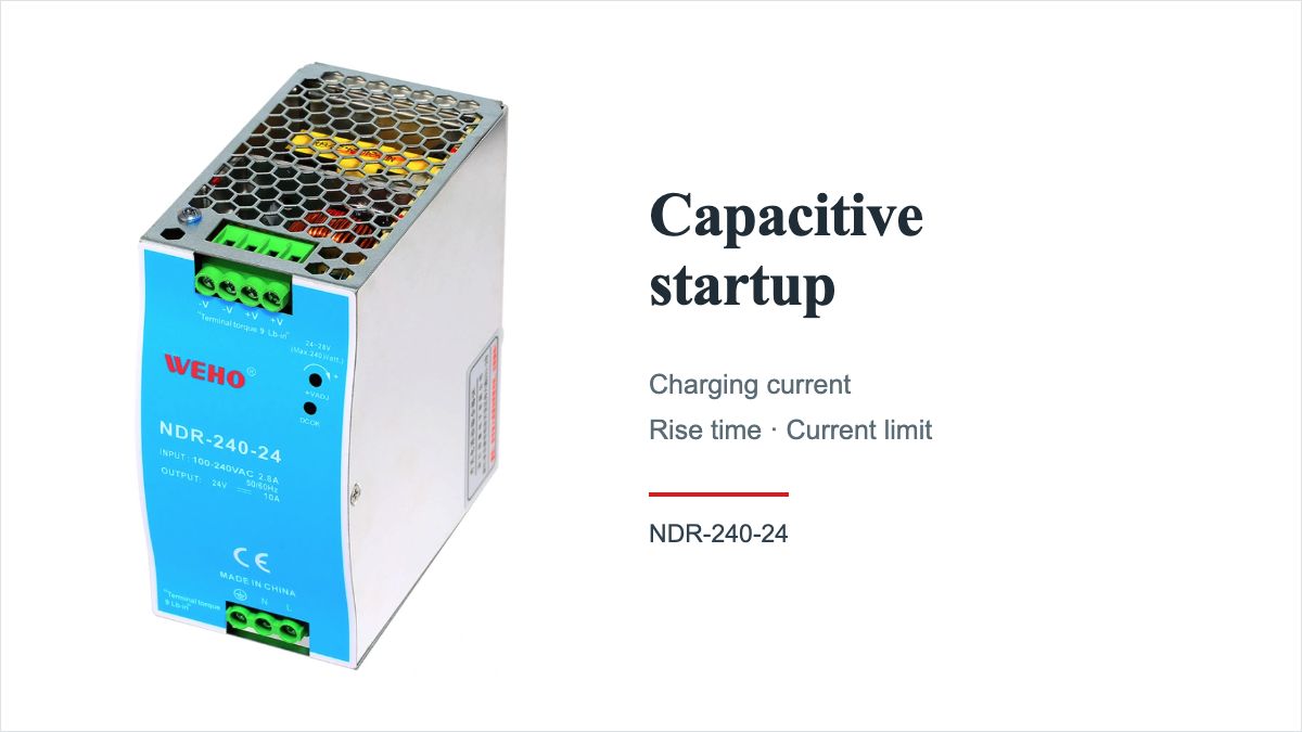
ที่ WEHO NDR-240-24 DIN rail power supply is a concrete candidate to review when a cabinet project needs a nominal 24 V source. Its NDR-240 specification lists 24 V, 0–10 A for this output version. That current rating is one screening input; it does not establish an allowable external capacitance or a successful startup ramp.
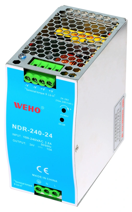
WEHO NDR-240-24 product photograph. The 24 V, 0–10 A specification is a screening reference; capacitive-load startup requires verification with the actual assembly.
View original photograph ↗
| Available starting point | Project evidence still needed |
|---|---|
| 24 V, 0–10 A published output | Permitted continuous load at the project’s input, temperature and mounting conditions |
| Calculated 7.14 A in the hypothetical 20 ms case | Actual source rise, current-limit behavior and active-load current during charging |
| Identified source model | Applicable revision, downstream protection, capacitance range and restart sequence |
Although 7.14 A is below the published 10 A rating, the calculation does not predict whether this supply produces that assumed ramp. Use the 24 V DIN rail sizing worksheet alongside the startup record so continuous demand and charging demand remain traceable.
Release a startup record containing the source revision, protection part, load assembly, capacitance range, control sequence, test conditions, and accepted limits. Preserve exceptions explicitly. Replacing one of those items may invalidate the original result even if the equipment’s running wattage stays unchanged.
Ask WEHO to review your capacitive-load startup requirements. Identify the proposed NDR-240-24 hardware revision and send the input range, required output, running current, connected capacitance, initial voltage, startup deadline, downstream protection, and restart interval. Request that revision’s startup current-limit behavior, overcurrent protection mode, and external-capacitance guidance, then verify the complete assembly under the agreed conditions. Include an existing voltage-and-current capture when available.




