Define which aspect of inverter output quality matters, and how it will be measured, before comparing results. RMS voltage, harmonic distortion and a short interruption are different observations. One screenshot cannot silently stand for all three.
For an engineer evaluating the WEHO WHP2000W inverter family, this guide produces a measurement plan tied to receiver requirements. It does not report a test of the unit or extend a linear-load specification to every receiver.
Translate “clean power” into specific quantities
Start with the connected receiver’s input requirements and the acceptance objective. Is the concern steady RMS voltage, frequency, harmonic content, a transient peak, or a brief gap that resets a controller? Give each concern its own quantity, observation method and limit source.
| Question | Useful record | What it cannot replace |
|---|---|---|
| Is steady voltage acceptable? | RMS value, method, load and interval | A short-event capture |
| How much low-frequency distortion exists? | Defined voltage THD method and harmonic range | An unscaled sine-wave screenshot |
| Does a load step upset the receiver? | Time-aligned voltage and receiver response | A long-interval average |
Do not select an attractive percentage after seeing the result. Agree the applicable receiver/manufacturer requirements before the evaluation.
Separate a waveform description from a numeric limit
The current WHP2000W product table describes pure-sine output, 2000 W rated power and 4000 W peak power. Its waveform-distortion row states THD<3% for a linear load. That condition must stay attached to the entry; it does not establish the same limit with an arbitrary nonlinear receiver.
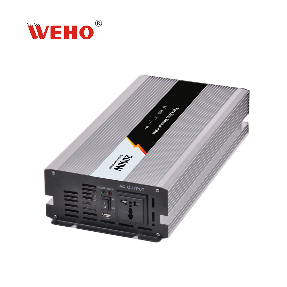
Ask for the matching revision’s test method and applicable output-quality conditions, including load definition and harmonic calculation. The published percentage does not specify every part of a repeatable observation. Report a measured result only after that measurement has actually been performed.
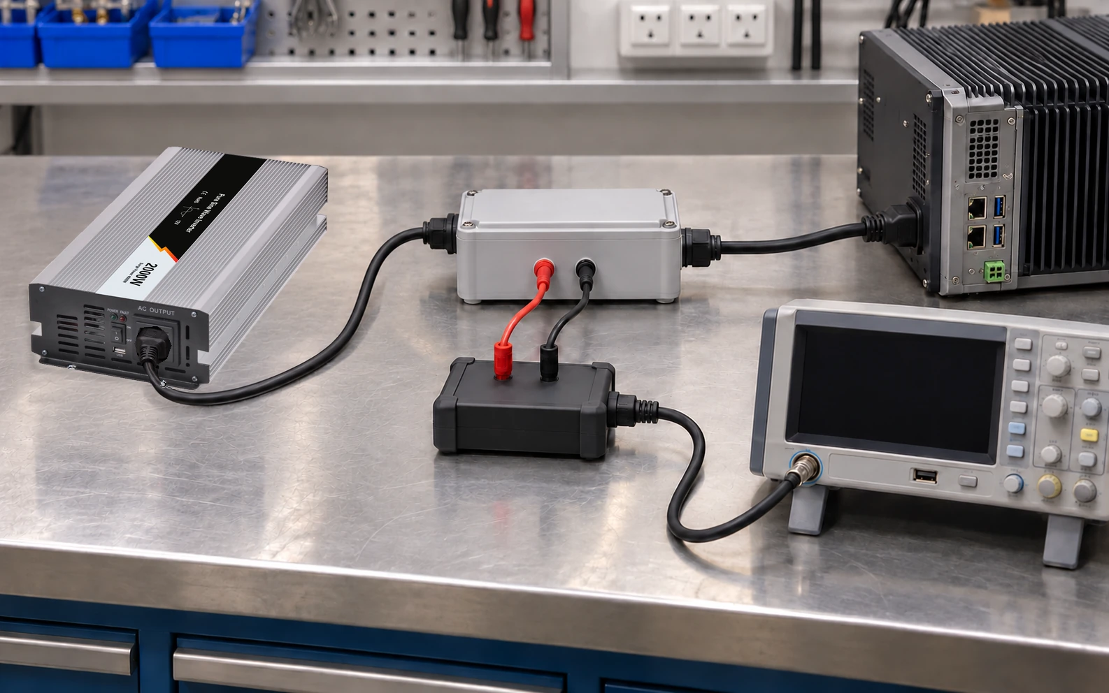
The official image preserves the 2000 W and 12 V example markings. It does not establish the ordered AC option or the outcome of any waveform test.
Specify the whole measurement chain
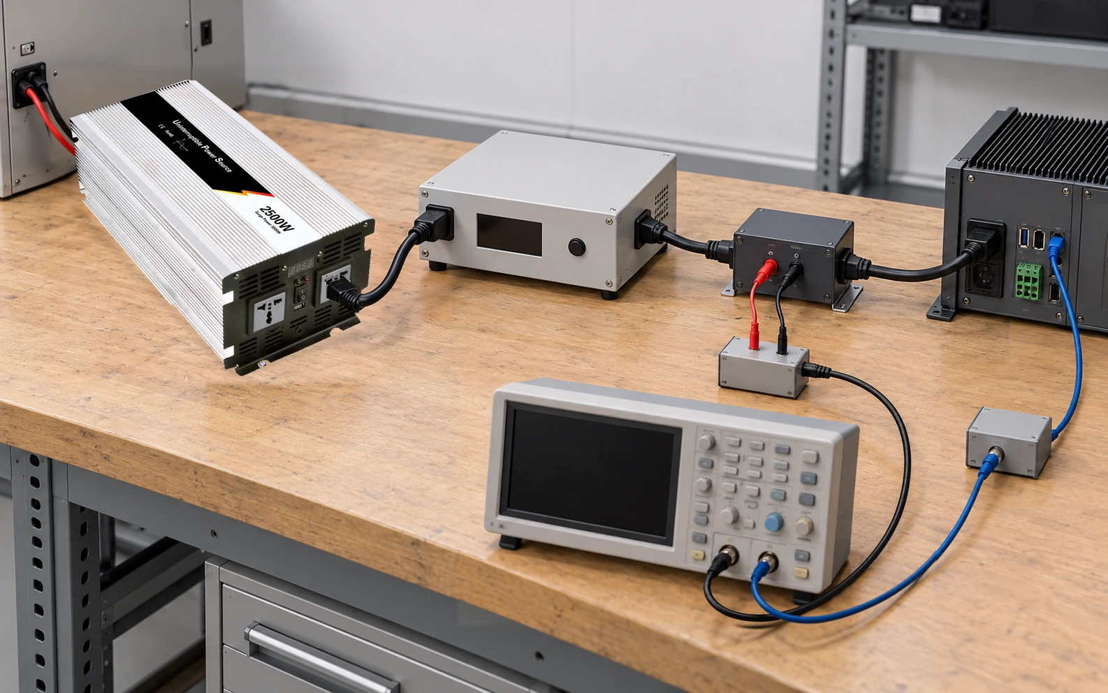
Record the acquisition instrument, voltage probe, current sensor where used, ranges, coupling, sample rate, effective bandwidth and filtering. Identify the measurement location and whether software applies additional averaging or harmonic limits.
Tektronix’s probe primer explains that bandwidth is a property of the probe-and-instrument measurement system. A high-bandwidth oscilloscope cannot recover information lost in an unsuitable probe. Its product examples are measurement guidance, not an inverter acceptance standard.
Use a qualified team and a rated connection method appropriate to the output arrangement. Do not attach an ordinary grounded probe in a way that creates an unintended source-to-earth connection. A suitably rated differential probe or isolated-channel instrument may be appropriate; verify differential voltage, common-mode voltage, measurement category and accessory limits for the actual circuit. A convenient waveform trace is not worth changing the circuit being assessed.
Give every distortion number a definition
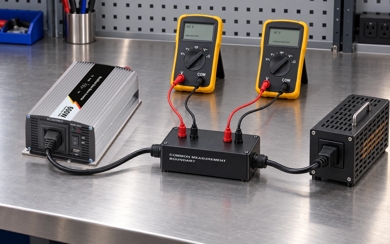
For a harmonic-voltage calculation, a common definition is the root-sum-square of the selected harmonic RMS values divided by the fundamental RMS voltage. State the included harmonic orders and measurement method. A meter’s total RMS display does not directly provide those components.
Hypothetical example: with a 230 V RMS fundamental, 3 V third harmonic and 2 V fifth harmonic, those included components yield sqrt(3² + 2²) / 230 × 100 = 1.57%. This is a fundamental-referenced ratio for the included components. Other omitted components could change a broader result. This example is not a WHP measurement or specification.
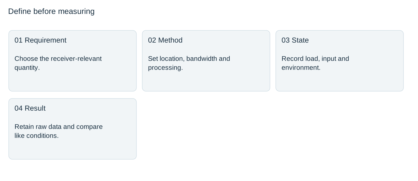

For fast transients, document acquisition bandwidth and record length separately. Filtering chosen for a stable harmonic report may hide the short event the receiver needs to tolerate.
Repeat the conditions that could change the output
Choose load states from the actual equipment: unloaded where relevant, representative steady operation, and the receiver’s important transitions. Record DC input at the inverter, output configuration and environment so a later result can be compared on the same basis.
Preserve raw data and the processing settings. If two instruments disagree, compare ranges, bandwidth, coupling, harmonic calculation and time windows before deciding the inverter changed. A screenshot cropped away from its scale and settings is weak comparison evidence.
The release file should pair each measured quantity with its agreed limit, method, conditions and receiver outcome. Leave untested states explicitly outside the result. This turns “pure sine wave” from an unbounded expectation into a useful, reproducible evaluation request.
Agree the output-quality evaluation
Send WEHO the WHP2000W configuration, receiver input requirements, proposed loads and measurement plan. Request the matching output-quality limits and their applicable conditions before accepting the results.
Inverter output-quality measurement plan
| Quantity / limit source | Load state | Location / bandwidth | Method / record reference | Result / coverage |
|---|---|---|---|---|
Blank project worksheet. Enter verified project data; example calculations above are not measurements.