



- An input-voltage range alone does not establish suitability for an IT earthing system.
- Check voltage across the input and voltage from each input conductor to protective earth separately.
- A first earth fault can change conductor-to-earth stress while the supply still sees its normal input voltage.
- Obtain exact-model IT-system permission and applicable conditions; another manufacturer’s approval does not cover WEHO.
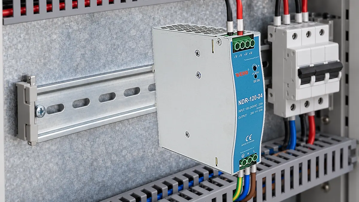
Why a normal input reading can leave the selection unresolved
A machine designer confirms the expected voltage across a power supply's input terminals and assumes the same unit is suitable on an IT mains network. The missing question is how each input conductor can move relative to earth, including a first insulation fault elsewhere in the network. The differential input reading does not describe that stress.
ที่ WEHO NDR-120-24 product reference is a candidate enquiry route in this article. The available product context does not establish IT-network approval or a permissible continuous input-to-earth voltage. Treat those items as model-specific selection requirements before releasing the candidate for an IT installation.
Identify the mains earthing arrangement precisely
IT here means an electrical earthing arrangement, not information technology equipment. The source's live system is isolated from earth or connected through an appropriate impedance, while required exposed conductive parts remain protectively earthed. It does not mean removing the protective-earth conductor from equipment designed to require it.
Obtain the network diagram and identify all live conductors, any distributed neutral, nominal voltages, permitted tolerances and the source's relationship to earth. A description such as “230 V industrial mains” does not establish these details. A line-to-line connection and a line-to-neutral connection can present different selection conditions even when both are discussed as single-phase loads.
IT networks also require system-level protection and monitoring provisions. Bender's IT-system standards explanation discusses first-fault behavior and its dependence on the installation conditions. Selecting a power supply neither completes that design nor authorizes continued operation after a fault without the required system provisions.
Separate three voltage questions
First, establish the voltage between the two conductors feeding the power supply. Compare its normal range and relevant events with the exact input requirements. This is the familiar differential-input check, but it is only one part of the assessment.
Second, establish the continuous voltage from each input conductor to protective earth in normal operation and the relevant first-fault states. The conditions may be asymmetric, and a terminal labeled N must not automatically be assumed near earth in every permitted supply arrangement. Ask the manufacturer which network connections the exact model allows.
Third, keep continuous operating voltage separate from transient and insulation-test values. A brief withstand test does not, by itself, establish a permissible continuous conductor-to-earth voltage or a mains-network approval. Record the relevant category, installation conditions and manufacturer instructions without converting one kind of specification into another.
The related WEHO insulation-coordination evidence guide addresses construction records rather than network permission. Use the applicable assessment documents alongside the input-network review, without estimating internal insulation paths from the cabinet image.
Calculate a hypothetical first-fault voltage shift
Consider an ideal balanced three-phase IT source with 230 V RMS line-to-line, no distributed neutral and equal healthy phase-to-earth coupling. A generic input is connected between L1 and L2. This is a theoretical voltage example, not a wiring recommendation or an approved connection of NDR-120-24.
Under the stated symmetric healthy assumptions, each phase is approximately 230 ÷ √3 = 132.8 V RMS relative to earth. The input between L1 and L2 still receives 230 V RMS. Actual healthy conductor-to-earth voltages can differ when leakage paths and capacitances are unbalanced, so the symmetric value must not become a field assumption.
Now assume an ideal low-impedance first fault connects L3 to earth. L1 and L2 are each approximately 230 V RMS relative to earth, while their line-to-line difference remains 230 V RMS. The conductor-to-earth magnitude has increased by a factor of √3, although the voltage across the generic input has not changed.
| Idealized network condition | Across generic L1–L2 input | L1-to-earth / L2-to-earth | Selection implication |
|---|---|---|---|
| Healthy, symmetric coupling | 230 V RMS | 132.8 V / 132.8 V | Still establish actual permitted earth stress |
| First fault from L3 to earth | 230 V RMS | 230 V / 230 V | Unchanged input does not mean unchanged earth stress |
| Same ideal fault case at +10% source voltage | 253 V RMS | 253 V / 253 V | Include permitted network tolerance |
Schneider Electric's IT fault-protection guide describes the rise in healthy phase-to-earth voltage during a first fault. The arithmetic here applies that principle to an explicitly assumed 230 V line-to-line system. It is not an assessment of touch voltage, fault current, protective-device operation or a complete installation.
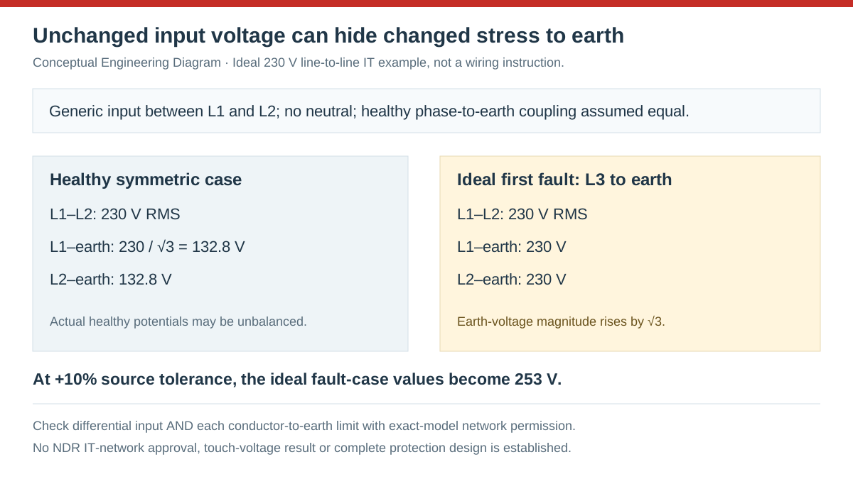
Swipe horizontally on a small screen, or open the full-size diagram.
Read a manufacturer's network permission with its limits
A useful instruction identifies the allowed network type and the related input-to-earth limit in the same document. For a concrete external example, the PULS CP20.481 installation manual explicitly permits TN, TT and IT mains networks while limiting continuous AC voltage between input terminals and PE to 300 V. That permission belongs to CP20.481 under its own instructions.
The PULS statement shows what a supplier response can look like; it is not evidence that NDR-120-24 has the same permission or limit. Even a candidate that satisfies one earth-voltage comparison must also meet its differential input, installation, temperature and other applicable requirements. Keep the exact model and document revision attached to every conclusion.
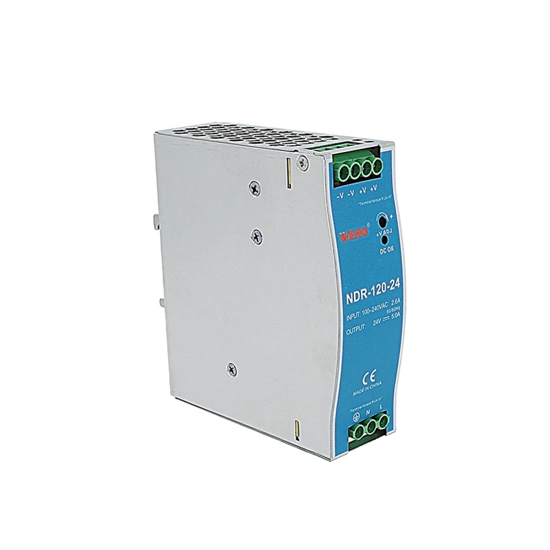
Avoid interpreting a terminal label or a general input range as an equivalent statement. Product photographs can identify the device and its visible connection points, but they do not establish internal input-to-earth component ratings. The cabinet illustration also does not depict an IT network, a first-fault state or an insulation-monitoring arrangement.
Build an input-suitability evidence record
Use a document review to resolve suitability before planning any energized investigation. Record the network arrangement, all relevant normal and fault-state conductor potentials, the candidate's written permission and the exact limiting conditions. A qualified installation designer must determine the actual fault cases and applicable requirements for the project.
- Identify the source arrangement. Obtain the network drawing, voltage definitions, tolerances and neutral distribution. Accept the record when the supply conductors and their relationship to earth are unambiguous.
- List the voltage cases. Document differential input and each input-to-earth voltage for the relevant operating and first-fault conditions. Save assumptions and the responsible designer's analysis; accept only a complete set of project cases.
- Request exact-model permission. Ask the manufacturer for allowed mains networks, continuous earth-voltage limits and associated instructions. Record the model and revision; do not release suitability from a similar product's data.
- Compare every applicable requirement. Check the documented cases against the candidate's input and installation conditions. Record each comparison and unresolved item; accept only the cases supported by the applicable documentation.
- Approve the complete installation separately. Have the responsible designer verify monitoring, protective earthing, fault response and required protection. Keep that assessment with the product evidence; a supply-selection pass alone cannot close the installation review.
Do not create a deliberate mains earth fault to reproduce the simplified table without a separately engineered and authorized test arrangement. The table is a selection calculation, not a commissioning procedure. Use approved documents and appropriate professional verification methods to establish the real installation conditions.
Prepare an NDR-120-24 IT-network enquiry
Send WEHO the NDR-120-24 candidate, source diagram, maximum differential input and each conductor's maximum continuous earth voltage in the defined cases. Ask for explicit model-specific permission and any restrictions that affect the proposed connection. Include the required installation and environmental conditions through the WEHO contact page before placing the candidate on the released BOM.
Frequently asked questions
Does an 85–264 V AC input range establish IT-network suitability?
No, a differential input range alone does not establish permitted conductor-to-earth stress or allowed network arrangements. Obtain the exact model's applicable installation permission and conditions.
Can input voltage stay normal while voltage to earth rises?
Yes, the hypothetical three-phase example shows that possibility after a first fault on another phase. Actual values require the project's network and fault analysis.
Does a short insulation withstand test establish a continuous earth-voltage limit?
No, those specifications describe different conditions. Use a documented continuous operating limit and the manufacturer's allowed mains arrangements for selection.
Can CP20.481 instructions approve a WEHO NDR model for an IT network?
No, CP20.481 permission applies to that PULS model under its instructions. Request separate evidence for the exact WEHO candidate and the intended installation.



