



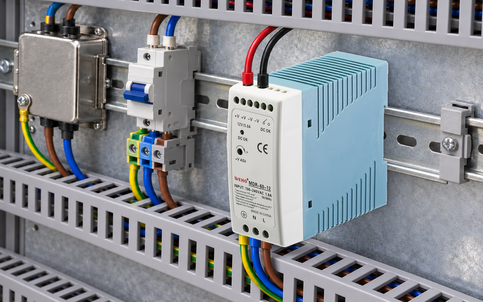
Do not approve an external AC EMI filter for an MDR-60-12 solely from its current rating or a catalogue attenuation curve. Define the panel’s emissions problem, choose a candidate for the actual AC input conditions, then evaluate the assembled supply, filter, bonding and cable arrangement together. The result applies to that configuration.
The MDR-60-12 is the 12 V, 5 A variant in the MDR-60 family. Those are output ratings; they do not mean that the AC filter should simply be selected as a “5 A filter.” This guide gives the panel engineer a pairing-test brief and a record for deciding whether a candidate filter helps without creating an unacceptable electrical or thermal condition.
Write the failure description before selecting hardware
ที่ WEHO MDR-60 product page states that the supply is a component and that final-equipment EMC must be reconfirmed. The correct MDR-60 specification sheet identifies the 12 V, 0–5 A version. A component claim does not establish the result for a panel with different wiring, loads or an added filter.
Start the test brief with the applicable final-equipment requirement, installation environment, affected frequency band and operating mode. Attach the baseline trace or report if one exists. If there is no measurement, record the suspected interference path as a hypothesis. An external filter cannot be credited with solving a failure that has not been defined.
Keep output ripple and AC-line interference as different tasks. A DC output measurement may be relevant to a sensitive receiver, but it does not replace a mains conducted-emissions test. Likewise, an AC-filter comparison cannot establish the receiver’s allowed DC ripple.
Screen the candidate against the actual input duty
TDK’s EMC-filter technical information defines rated current under specified conditions and calls for temperature derating where applicable. It also notes that non-sinusoidal input current can produce additional thermal loading. Use the candidate filter’s own voltage, frequency, current, temperature and overload conditions, together with the documented or measured panel input duty.
| Candidate check | Information needed | Hold the candidate if… |
|---|---|---|
| Voltage and topology | Actual mains range and the filter connection type. | The required supply system is outside the filter rating. |
| Current and temperature | Panel input current, waveform/duty and filter derating. | A DC output current is the only selection basis. |
| Startup and protection | Supply startup demand, upstream device and filter limits. | Short-duration duty or protection coordination is unresolved. |
| Mechanical and bonding | Filter maker mounting instructions and final layout. | The intended installation cannot meet those instructions. |
Ask the filter supplier for any missing condition rather than treating a larger ampere number as a complete substitute for application evidence. This article deliberately does not nominate a filter part number: no measured panel spectrum or exact installation has been supplied.
Compare the relevant interference mode
SCHURTER’s filter-measurement explanation separates common-mode and differential-mode insertion-loss arrangements. In its common-mode measurement, line and neutral are evaluated with respect to earth; the differential-mode measurement concerns line versus neutral. A curve for one mode is not evidence of the other mode’s attenuation in your assembly.
Use those curves to shortlist candidates, then retain the actual test setup and layout in the comparison. A catalogue curve belongs to its stated measurement arrangement. Do not subtract its dB value from a failing panel trace and publish the resulting arithmetic as a measured pass.
Run a controlled baseline and candidate comparison
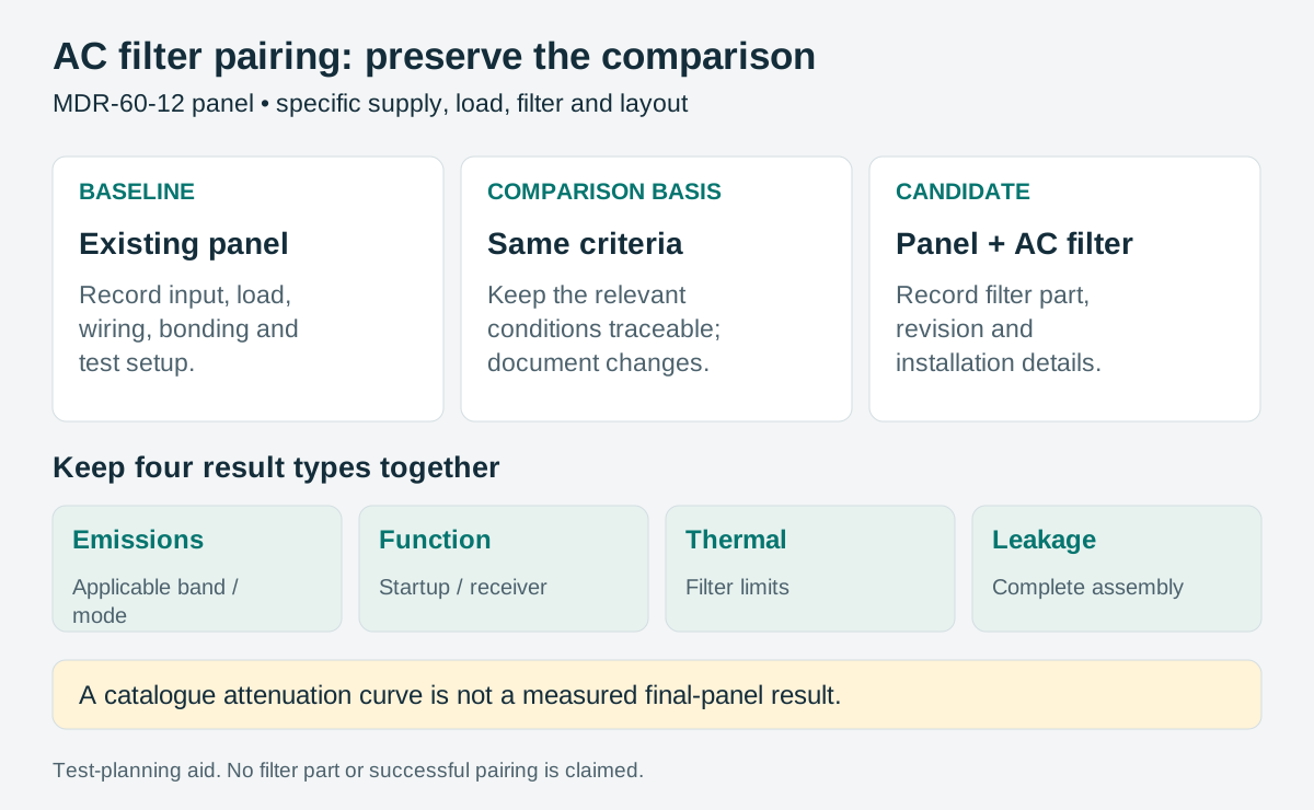
Freeze the supply revision, output setting, load state, input conditions, enclosure, cable routes and test arrangement. Change the intended filter configuration and its necessary installation details, documenting those changes. Keep a baseline record so the comparison can be repeated if a later production unit behaves differently.
| Record | Baseline panel | Panel with candidate filter |
|---|---|---|
| การกำหนดค่า | Supply, loads, bonding and cables identified. | Filter part/revision and installation drawing added. |
| Emissions result | Trace/report, mode, band and operating state. | Same comparison conditions; record every relevant result. |
| Function and startup | Receiver behavior and startup event recorded. | Repeat at the defined demanding input/load states. |
| Thermal observation | Supply and enclosure conditions identified. | Filter temperature assessed against its own limits. |
| Leakage / protective-conductor review | Applicable method, result and circuit identified. | Repeat for the complete modified assembly. |
Judge the candidate against the applicable requirement and the machine’s functional criteria, not merely whether one peak becomes lower. If a change improves one band but worsens another or changes startup behavior, keep both results in the decision record.
Keep leakage evidence with the final assembly
TDK’s technical guidance treats the stated filter leakage figure as a comparison aid and calls for evaluation of the complete equipment or installation with the applicable measurement method. Therefore, a simple sum of component catalogue values is a screening budget, not the completed assembly result. Preserve protective-earth provisions; do not disconnect a protective conductor as an interference remedy. See the TDK discussion of leakage-current evaluation.
Record the filter variant, its leakage-data conditions, other relevant components, the protective device and the result from the qualified final-equipment evaluation. Do not select or uprate an RCD solely to hide unexplained trips. Any protective-device decision belongs in the equipment’s electrical design and applicable requirements review.
Release the pairing with its exact configuration, report references and limits. Reopen it when filter capacitors or variants, the power supply, cabinet bonding, cable routing or connected equipment changes. The useful purchasing description is an approved part and installation revision backed by a pairing record, rather than “add a good EMI filter.”
Use the project record
Open the blank MDR-60-12 and AC EMI filter pairing record to record your conditions, evidence and decisions. The worksheet contains no pre-approved result.
For an MDR-60-12 panel, send WEHO and the proposed filter supplier the input conditions, load states, layout and actual test concern. Request the current supply documentation and the filter’s application limits before freezing the pair.




