SELV versus PELV is a system-protection decision; a nominal 24 V label cannot settle it. Before intentionally bonding an output conductor to earth, identify the applicable protective measure and every connection that could establish an earth reference. Then confirm the complete arrangement against the relevant installation and equipment requirements.
On this page
The practical output of this review is an interface map and a controlled bonding decision. It covers the supply, powered devices, communication connections and servicing equipment. It is not a proposal to add or remove an earth connection solely to reduce noise.
Separate output voltage, protective separation and earth reference
Schneider Electric’s extra-low-voltage guidance describes SELV and PELV as protective arrangements with separation requirements and different earth-connection conditions. In that installation context, SELV excludes intentional connections of its live conductors to earth, while PELV can include an earthed secondary point. The review must also cover exposed conductive parts and separation from higher-voltage circuits. Low voltage by itself does not supply the remaining conditions.
ที่ IEC 60364-4-41 scope addresses protection against electric shock in low-voltage installations. The applicable equipment standard, installation environment and national adoption must also be established for the project. Do not borrow a voltage threshold from an unrelated product standard or treat all dry, damp and accessible installations alike.
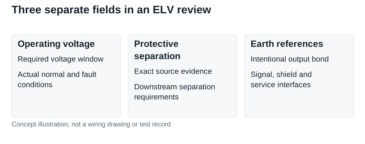
Record three separate statements: the allowable operating voltage, the evidence for the required separation, and the permitted connection to earth. A source may have documentation supporting use in a protective arrangement without every possible downstream assembly meeting that arrangement.
Map every interface that can change the reference
Start at the supply output and follow both conductors to all loads. Add communication ports, shields, analog signals and external equipment. Distinguish a shield termination from a signal-common connection; do not assume that the two are internally separate or bonded without the device documentation.
Pay attention to connections made only during installation or maintenance. A grounded programming computer, test instrument or external interface can change the reference conditions. Identify the actual equipment and approved measurement method before attaching it; a general-purpose earth-referenced probe is not automatically suitable for an unknown floating circuit.
| Interface | Question for the review | Evidence to retain |
|---|---|---|
| Supply output to chassis | Is a bond allowed, required or prohibited in this arrangement? | Exact supply instructions and approved system drawing |
| Signal common to another device | Does the connection introduce a second earth reference? | Port isolation/reference documentation |
| Cable shield | Where is the shield bonded, and is it connected to signal common? | Device and installation instructions |
| Service equipment | Does connecting it alter the protective arrangement? | Approved service/test setup |
Work through the effect of one proposed bond
Hypothetical reference example: an isolated source maintains 24 V between its positive and negative output conductors. Before an intentional reference is established, that differential voltage alone does not specify either conductor’s voltage relative to earth.
If an approved system design bonds the negative conductor to its earth reference, the ideal circuit reference becomes 0 V at negative and +24 V at positive. This simple reference calculation does not demonstrate protective separation, acceptable fault behavior, touch-current performance or compliance. Those require the appropriate evidence and complete system assessment.
Now add an external device whose signal common is connected to earth. If that common is also tied to the source negative, it creates another connection to the same reference. The engineering question becomes whether the intended protective arrangement and permitted current paths remain valid. Do not solve it by removing a protective-earth conductor from equipment that requires one.
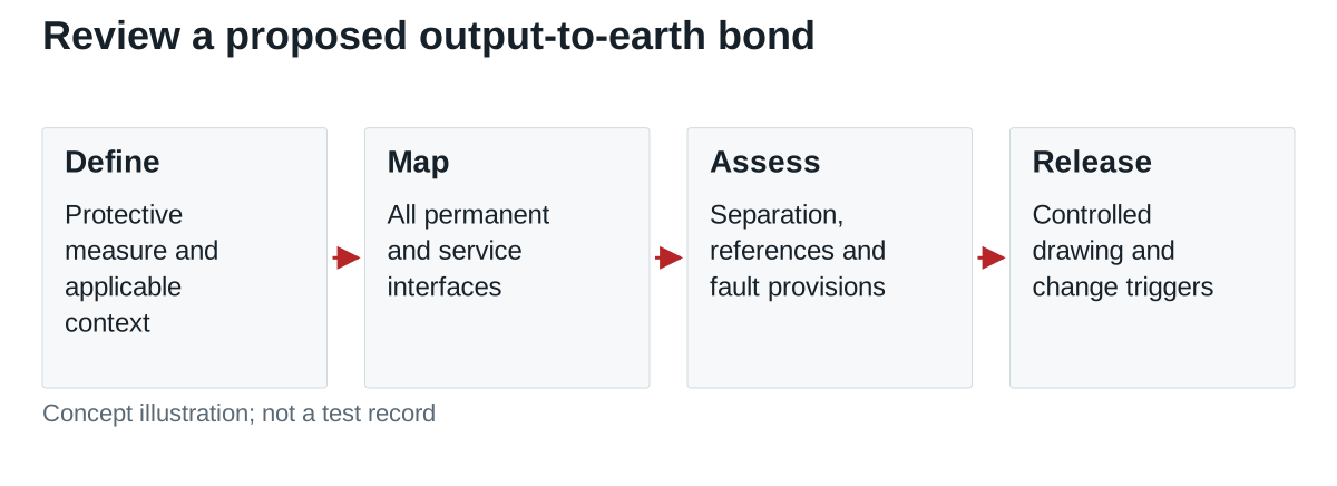
Record where the intentional bond belongs, how other references are handled, and how the configuration is inspected. Where an ungrounded arrangement is required, document the applicable fault-detection and protection approach instead of assuming that absence of a bond makes every fault harmless.
Identify the NDR-240-24 terminals before the bond review
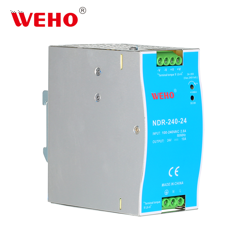
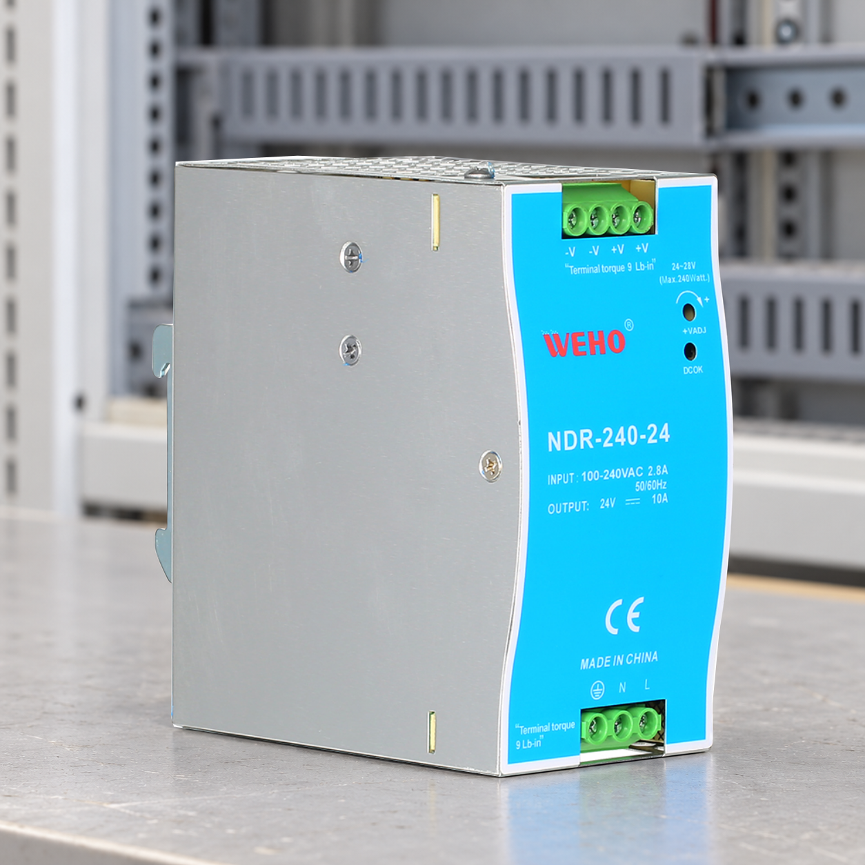
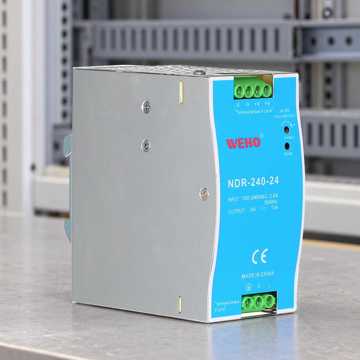
ที่ WEHO NDR-240-24 photograph shows protective-earth, N and L markings on the bottom input connector, separate from −V, −V, +V and +V markings on the top output connector. Put the input protective-earth connection and any proposed output reference on separate rows of the system map. Identify the individual output-terminal positions as well as their markings so that downstream returns and any system-approved bond remain traceable. The duplicated −V labels and physical separation from the input block do not by themselves establish the internal connections or authorize a jumper.
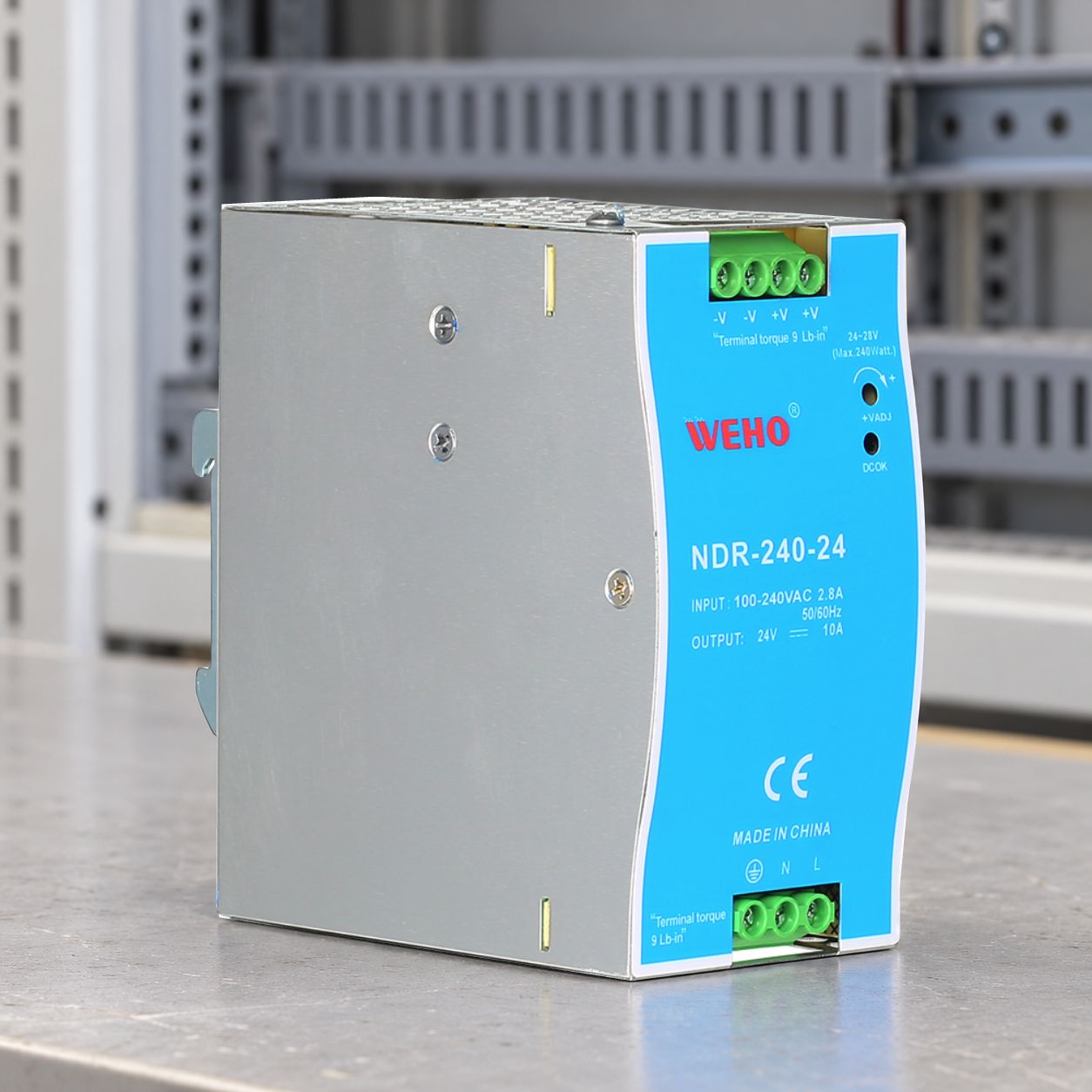
Use the applicable NDR-240 specification to identify the source, then request its controlled separation evidence and permitted output-to-earth conditions for the actual assembly. Neither the enclosure photograph, a withstand-test entry nor a nominal 24 V label independently establishes SELV/PELV classification of the complete system.
Link the proposed reference to the downstream port map, required protective measure and approving reviewer. A change of supply, communication module or service fixture can reopen that decision. The pictured unit is a specific review candidate, not a claim that it is interchangeable with a different 240 W model.
Release a drawing that remains understandable in service
Give the protective measure a named owner. The electrical designer identifies the intended arrangement, the compliance reviewer confirms the applicable requirements, and production receives a drawing that locates intentional bonds and separates them from incidental connections. An unlabeled jumper in a cabinet is a poor long-term record of that decision.
Include the revision of every interface document used. Where a connection remains uncertain, obtain its manufacturer’s clarification or isolate the unapproved interface from the proposed arrangement until the review is complete. A resistance reading alone may not reveal all operating-state paths through connected electronics.
| Release deliverable | Required content |
|---|---|
| Protective-measure statement | Applicable standard/context, intended arrangement and approving owner |
| Reference map | Output conductors, chassis/earth, signal ports and service connections |
| Source evidence | Exact model/suffix, separation evidence and permitted output referencing |
| Change trigger | Review after source, port, bond or service-method changes |
Send WEHO the proposed output-reference drawing with the exact supply model, destination market and relevant equipment standard. Ask for source-specific conditions that your system reviewer can evaluate, rather than requesting a blanket declaration based only on output voltage.