



TX4-H Wiring and Setup: An OEM Configuration and Acceptance Checklist
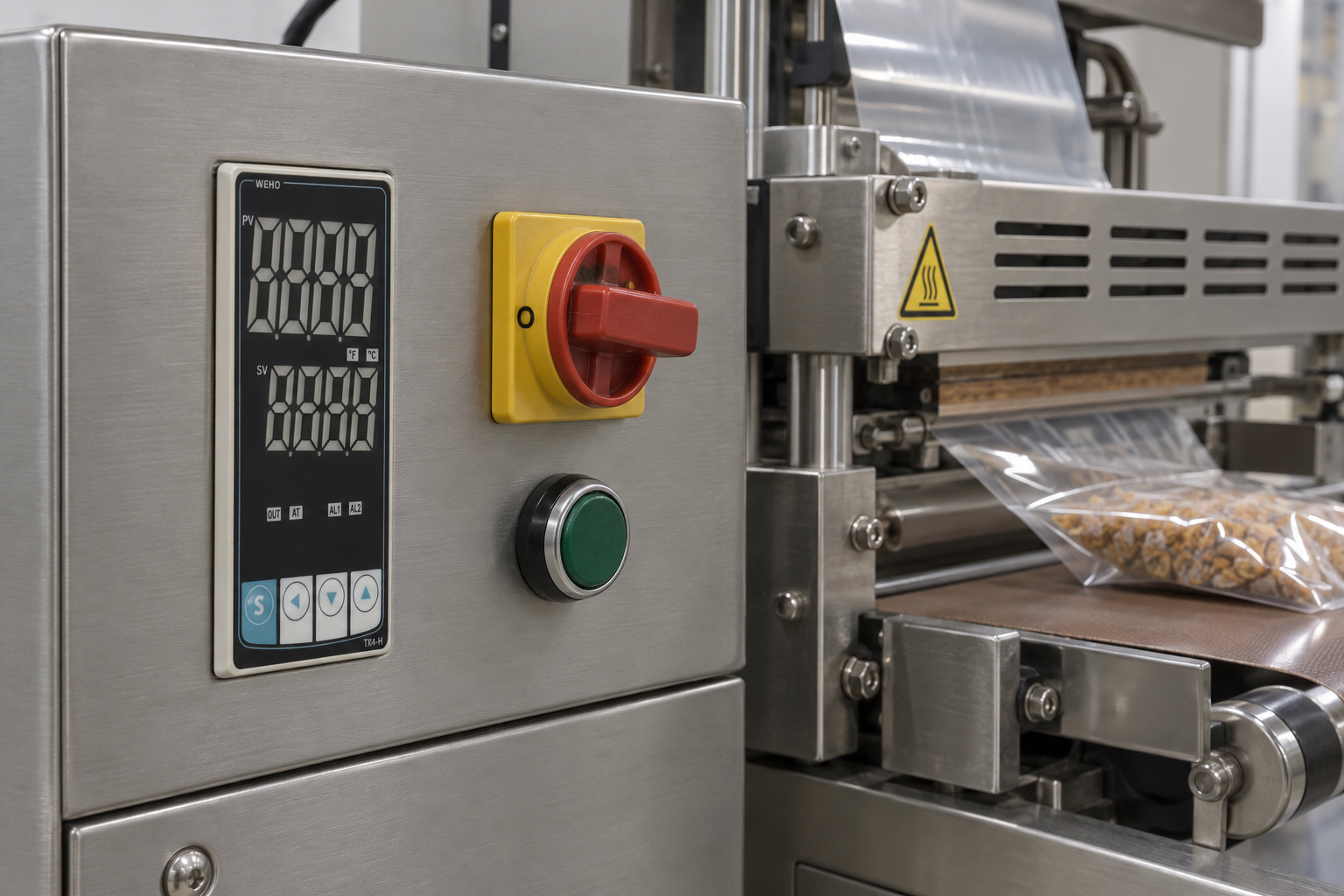
For an OEM panel, TX4-H wiring and setup should be treated as a controlled configuration task: identify the delivered suffix, map the terminals from the matching drawing, select the input and output functions, then record acceptance results before releasing the machine. Copying settings from a square controller or buying by “PID, 48 mm wide” is not sufficient.
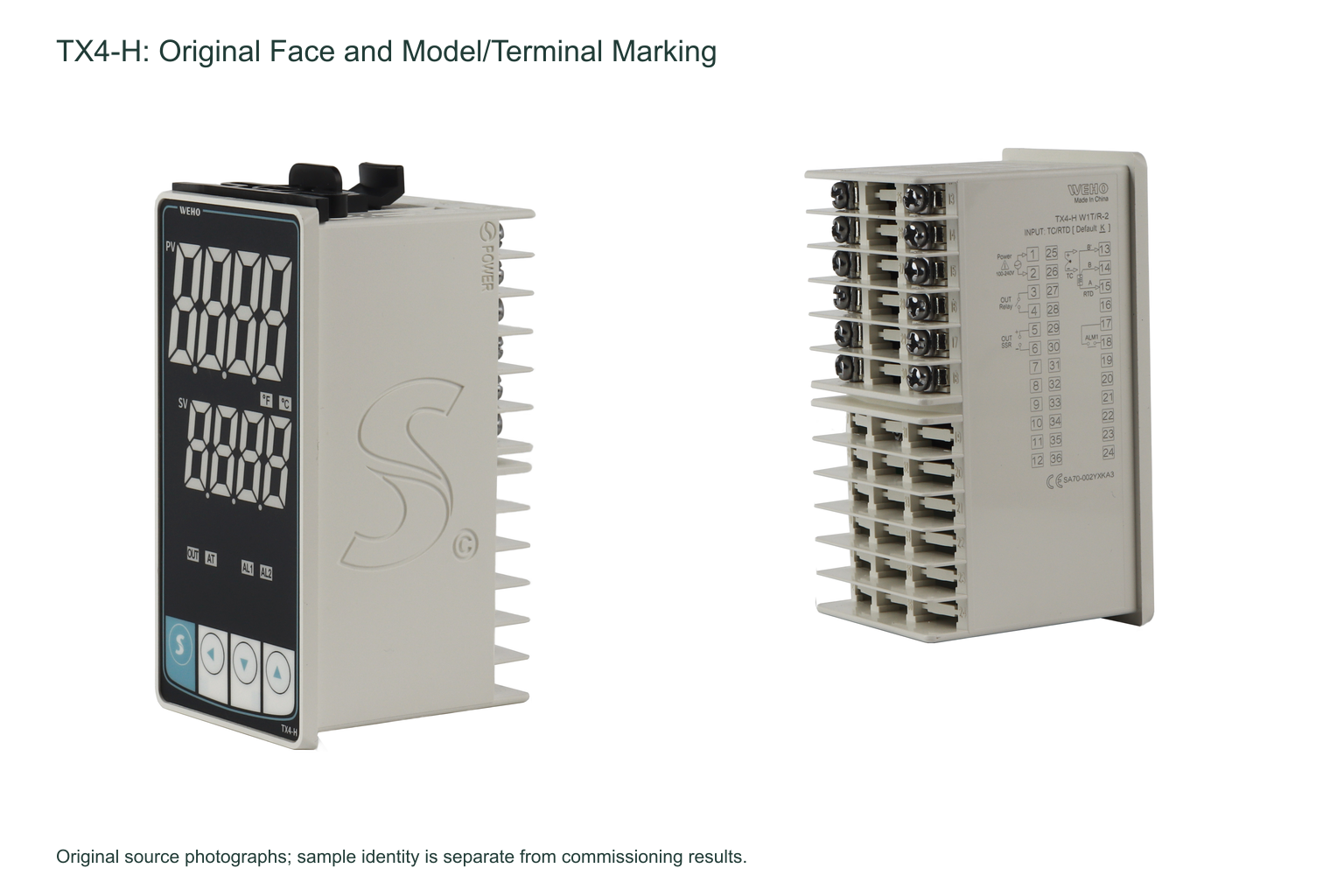
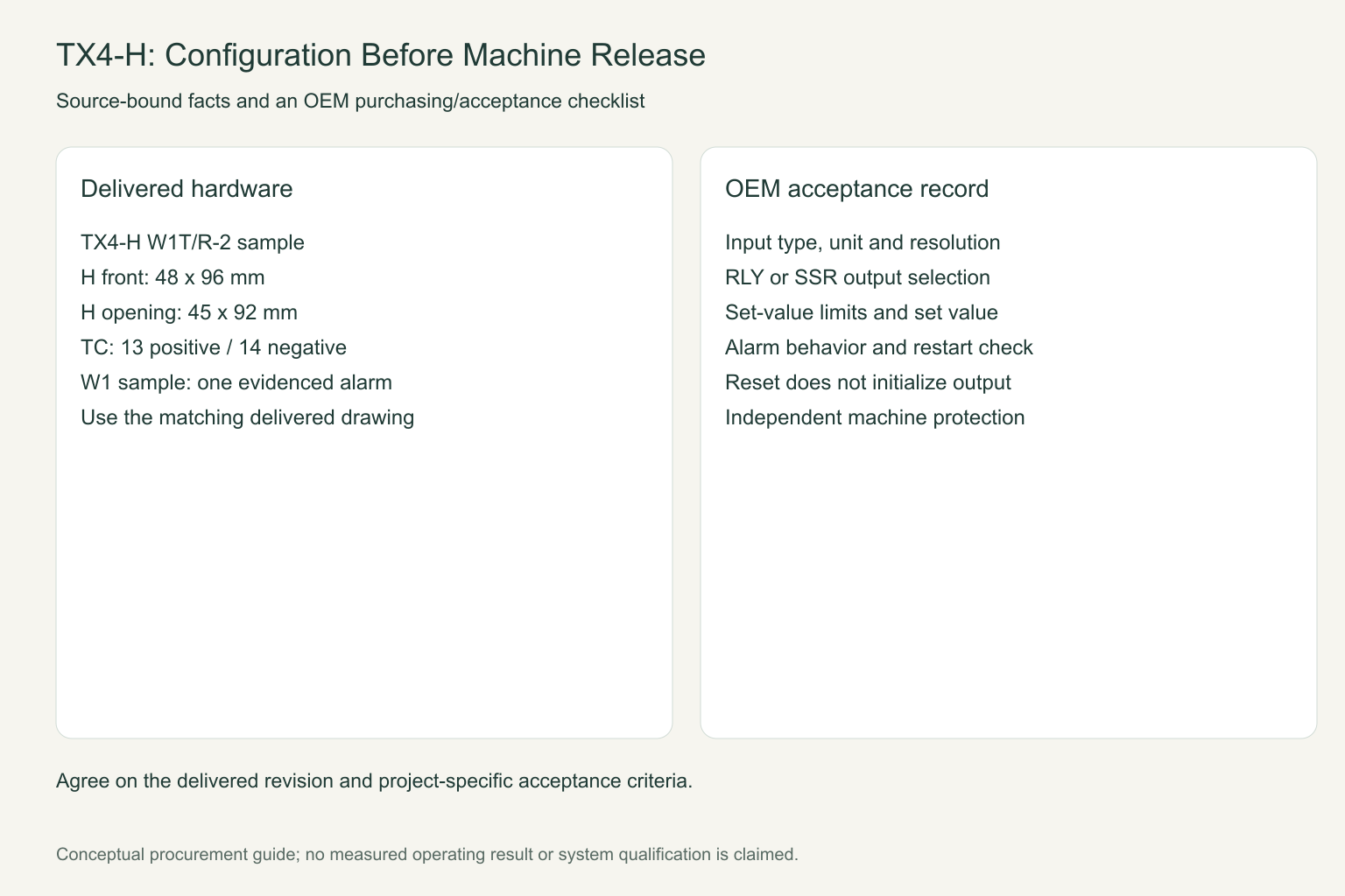
The sample used here is TX4-H W1T/R-2, a tall panel-mounted controller. The matched TX4 manual identifies H as a 48 × 96 mm face with a 45 × 92 mm panel opening. These are revision-bound dimensions, not permission to machine a replacement panel without checking the delivered drawing.
Make the quotation identify the configuration
Write the complete model on the purchase specification, together with supply voltage, sensor type, control-output interface and fitted alarm requirement. In the matched ordering table, W denotes relay/SSR drive, 1 denotes Alarm 1, T/R covers the listed thermocouple and RTD inputs, and supply code 2 denotes 100–240 VAC/DC. Confirm that the actual nameplate and the offered revision agree; a family feature list does not prove every option is installed.
The photographed H unit shows Alarm 1 on terminals 17/18. The manual also draws a family Alarm 2 circuit, but that is not evidence of a second fitted alarm on this W1 sample. A machine needing two independent alarm contacts must not be released on the assumption that a printed front indicator supplies the missing hardware.
Use the H terminal map, not an S drawing
| Interface | Matched H manual | OEM acceptance question |
|---|---|---|
| Controller power | 1/2 | Does the delivered supply code match the panel branch? |
| Relay control output | 3/4 | Does the load interface meet the applicable contact rating and duty? |
| SSR drive | 5 positive / 6 negative | Does the selected SSR input accept the documented drive? |
| Thermocouple input | 13 positive / 14 negative | Are input type, polarity and extension materials correct? |
| RTD input | 13 B′ / 14 B / 15 A | Is the specified three-wire circuit correctly implemented? |
The manual lists a relay rating of 250 VAC, 3 A and SSR drive of 12 VDC ±2 V, no more than 20 mA. SSR drive is a control signal, not a heater-power output. Select the external switching and protective equipment from the real heater circuit; neither of these controller figures establishes the complete machine’s power capacity or safety function.
Freeze the setup sequence for repeat production
The manual recommends configuring Parameter Group 2 before Group 1 and the set value. Start with input type, temperature unit and resolution; then confirm the set-value limits, output selection and heating/cooling mode. Changing input type, unit, decimal-point setting or set-value limits initializes the set value, so a changed parameter must trigger a fresh set-value check.
Record whether the control output is RLY or SSR. The manual suggests control cycles of 20 seconds for relay output and 2 seconds for SSR output; those are starting recommendations, not universal process settings. Importantly, parameter reset does not initialize the output-selection parameter. A reset controller therefore still requires explicit output verification.
Define sample acceptance before approving a lot
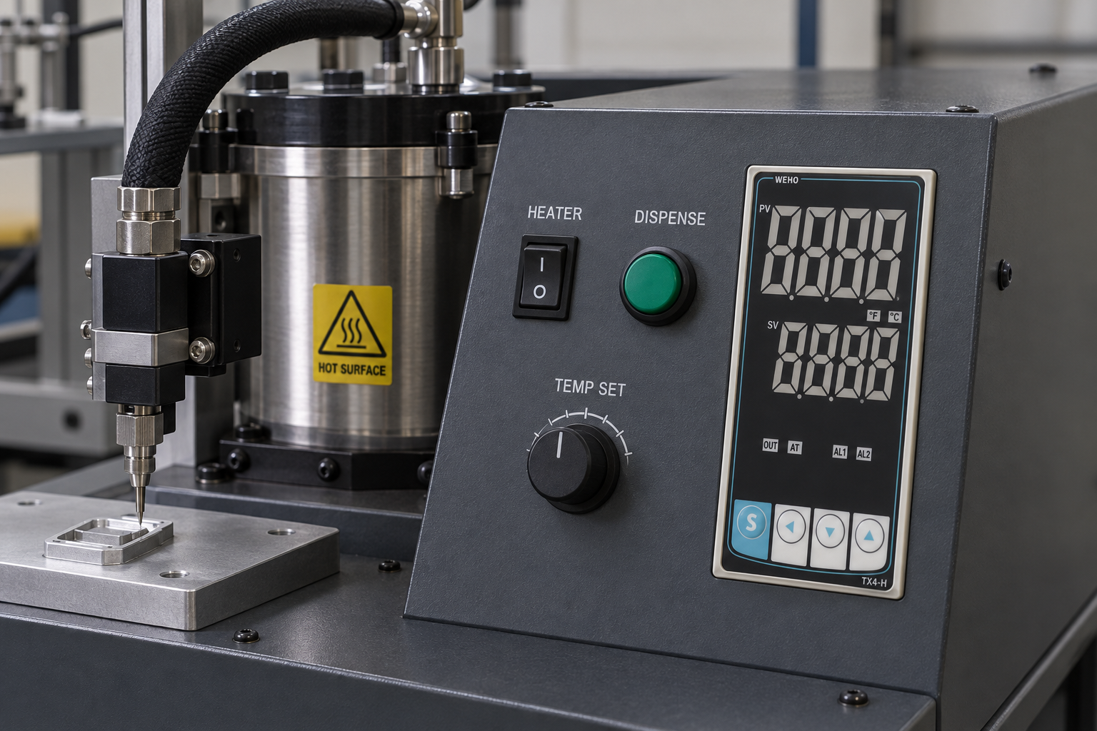
Use a configuration sheet covering the exact suffix, delivered drawing, sensor simulator or reference input, selected output, set value, alarm behavior and power-loss recovery. Record the expected and observed response for each test. Perform electrical work with the machine isolated and qualified personnel responsible for commissioning; unexpected heating must be prevented while configuration is incomplete.
Separate controller acceptance from process acceptance. A correct display and output do not prove heater distribution, workpiece temperature or an independent overtemperature shutdown. The manual calls for fail-safe protection where controller failure could cause serious harm. Identify that protection in the machine design rather than naming the normal PID controller as the safety device.
What an OEM should send with an enquiry
Provide panel opening and available depth, input supply, sensor type and range, output interface, alarm count, heater-control architecture, target market, sample quantity and expected production demand. Ask for the offered full model, revision-controlled drawing, terminal schedule and a configuration record suitable for incoming inspection.
Compare temperature-controller families in the WEHO product catalogue และ request TX4-H configuration confirmation. Availability, lead time and commercial terms should be confirmed in the actual quotation.
Buyer questions
Can an H controller replace an S controller by copying the wiring?
No. Their panel geometry and sensor/alarm terminal numbering differ. Use the delivered model’s circuit and requalify the affected panel connections.
Does a factory reset produce a known output configuration?
Not by itself. The matched manual specifically excludes control-output selection from reset, so RLY/SSR must be checked and documented.




