



MDR-60W gate controller power should be selected for an identified control branch, not for an assumed barrier motor. The WEHO MDR-60-12 specimen provides a documented 12 V, 5 A reference and a separate DC OK contact function. An OEM can use those facts to review a conditional 12 V controller interface, but they do not establish actuator capacity, backup operation or a gate safety function. The useful decision is which equipment belongs on this branch and what evidence must remain valid when the gate changes state.
Separate controller electronics from the movement circuit
Start with the actual gate or barrier controller’s input specification. If it requires a different supply voltage, the photographed MDR-60-12 is not made compatible by changing a caption. List only confirmed 12 V devices assigned to the proposed branch: the controller electronics and any documented auxiliary interfaces. Keep the motor, brake, heater, battery charger and unrelated accessories outside that list unless their own requirements and the released equipment design explicitly include them.
The official WEHO MDR-60 page includes the 12 V, 5 A variant. The actual source label reads MDR-60-12, 12V/5.0A and INPUT100–240VAC1.8A, 50/60Hz. Preserve the slash and original trademark in images. The retained specification’s broader operating-input range is a separate record, not a reason to redraw the physical nameplate.
Review the controller’s real operating states
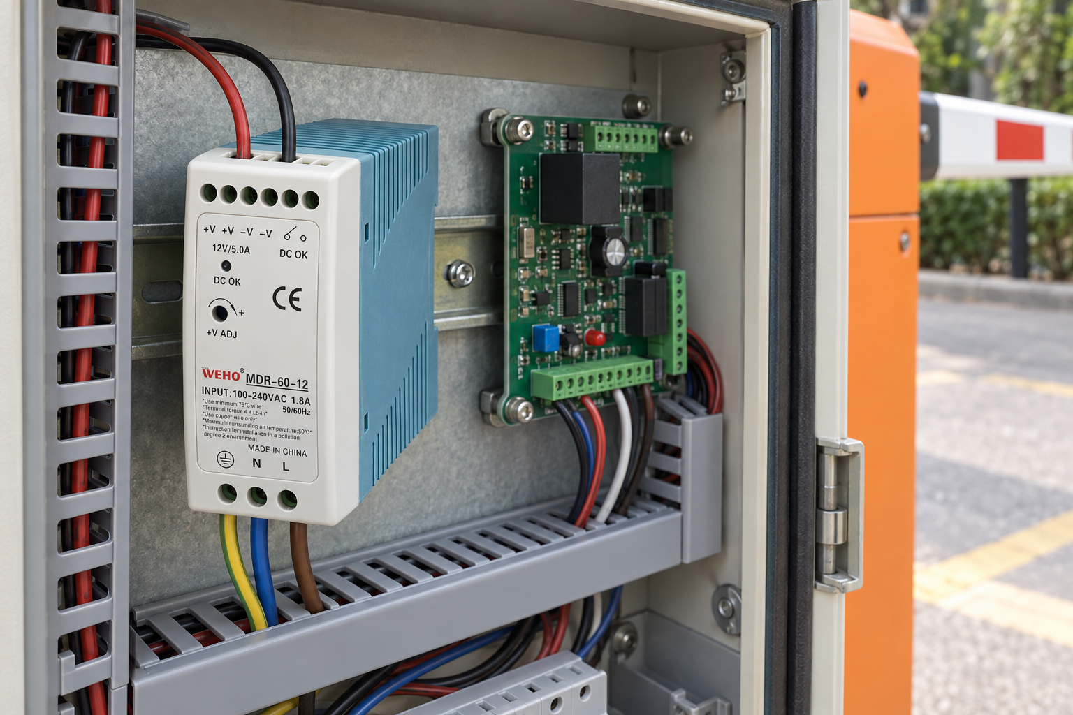
A branch requirement should capture the controller’s documented normal demand and any relevant initialization, accessory or recovery state. Ask whether the equipment must retain communication, record position or remain energized when a movement command is inhibited. These are questions for the exact controller and complete gate design, not capabilities inferred from the supply’s wattage.
Use a state sheet that identifies the real receivers, their allowed input limits and the intended simultaneous combinations. Leave current values and acceptance thresholds unresolved where the equipment maker has not supplied them. Do not invent a motor surge allowance, automatic restart behaviour or a guaranteed open/close sequence to make a nominal 5 A rating seem adequate.
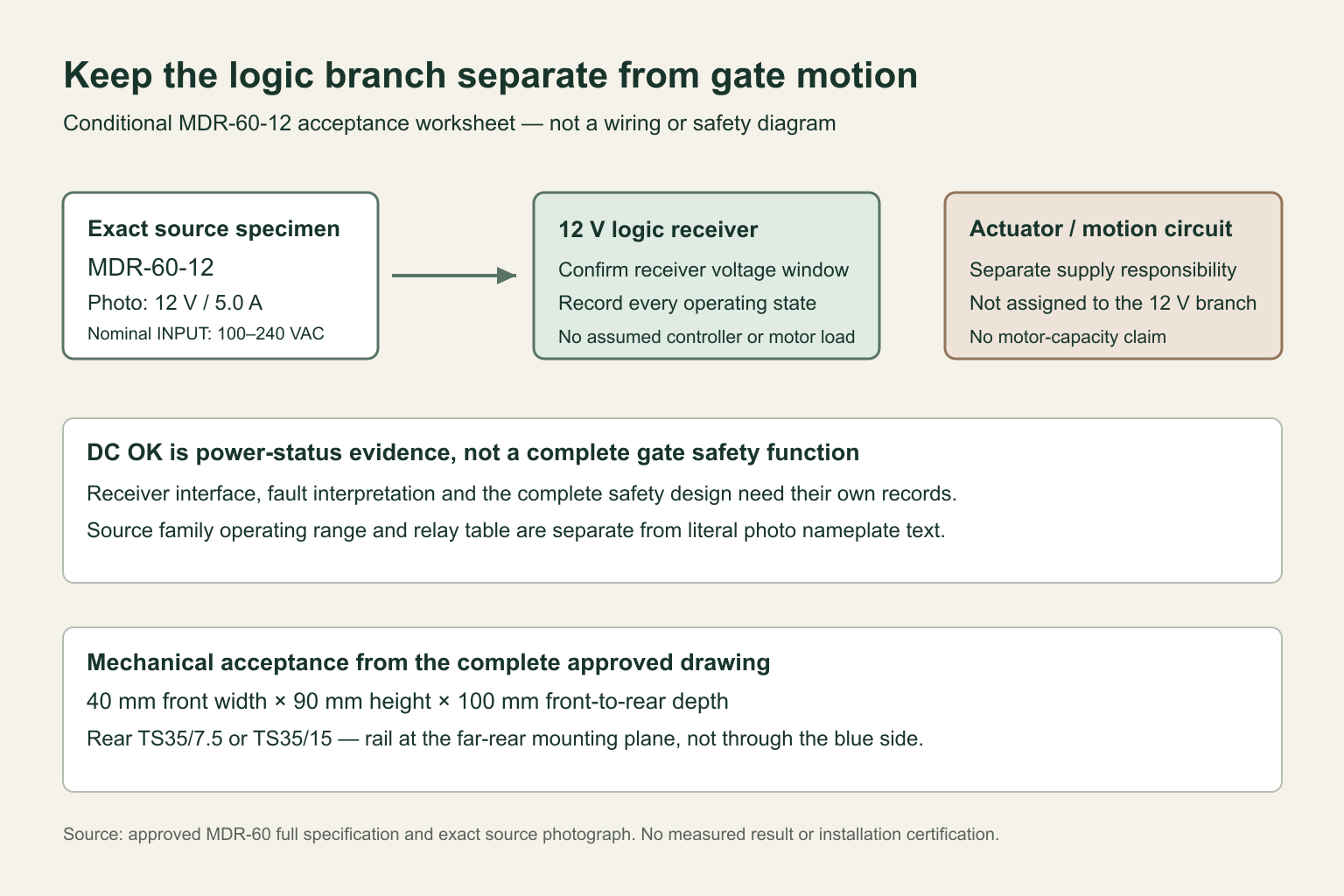
| Evidence boundary | Question to close | What the supply label does not prove |
|---|---|---|
| Controller branch | Does the exact receiver accept the proposed 12 V source under its intended states? | Compatibility with every gate controller |
| Movement circuit | Which supply and driver own motor or brake demand? | Capacity for an unidentified actuator |
| Power status | How will the documented contact interface be interpreted? | A certified safety interlock |
| AC loss and recovery | What must the complete gate system do? | Battery backup or a verified restart result |
Treat DC OK as a defined interface, not a safety decision
The approved mechanical/electrical sheet distinguishes the two DC OK contact terminals from the four DC output terminals. Its relay table describes contact state in normal power and power-off/DC-fault conditions. That supports a power-status interface discussion; it does not turn the contact into a gate-position sensor, obstruction detector or safety-certified stop circuit.
Before integrating the contact, obtain the exact interface rating, receiving-input requirements, isolation arrangement and equipment logic from the responsible designers. Keep the final gate safety assessment outside this component-selection article. No switching threshold, response time, gate protection category or fault-detection coverage is established here.
Preserve the source-supported mounting and terminal anatomy
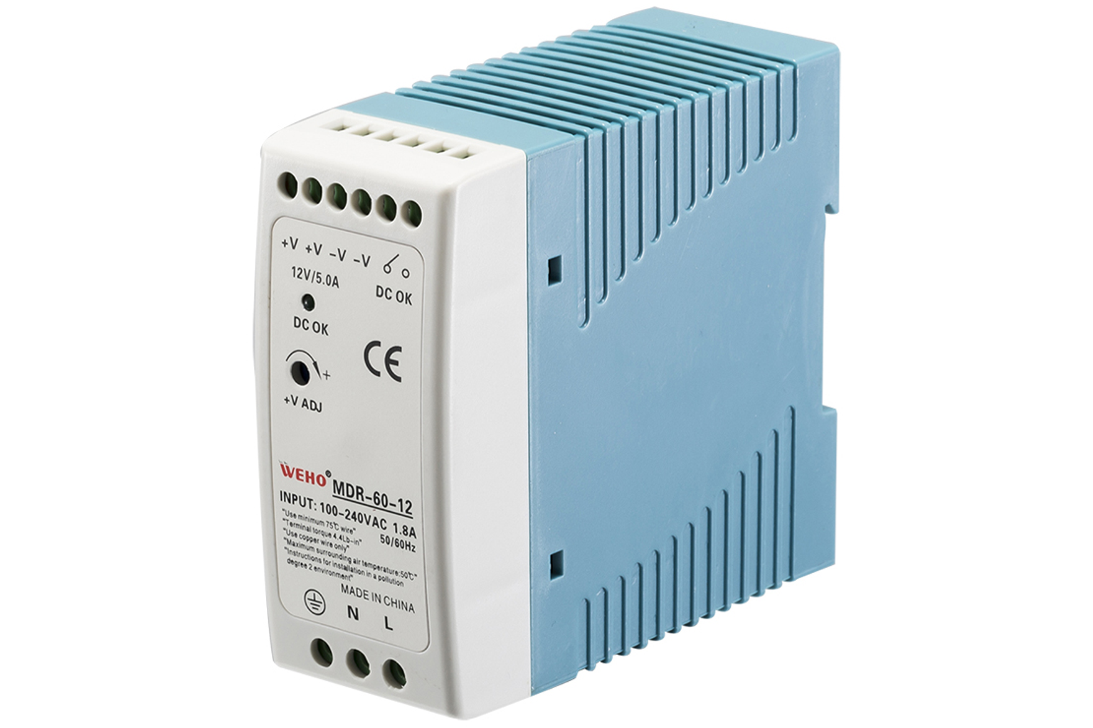
The complete MDR-60 drawing identifies a 40 mm front width, 90 mm upright height and 100 mm front-to-rear depth, with TS35/7.5 or TS35/15 rear rail mounting. The rail must be behind the narrow rear plane; it does not pass through the long blue sidewall. The source has six upper positions and three lower positions, with separate screw-access openings and conductor-entry windows. A wire inserted into a screw-access hole or ventilation slot is not an acceptable interpretation.
The exact specimen has a narrow white front, blue ribbed body, an original adjustment marking and a DC OK indicator. Keep those features unchanged in a source-referenced application scene. The image can illustrate a controller-compartment fit or a verified connection definition; it cannot invent the controller’s voltage, conceal an incorrect label or imply that the photographed gate has passed acceptance.
Make the replacement packet specific enough to use
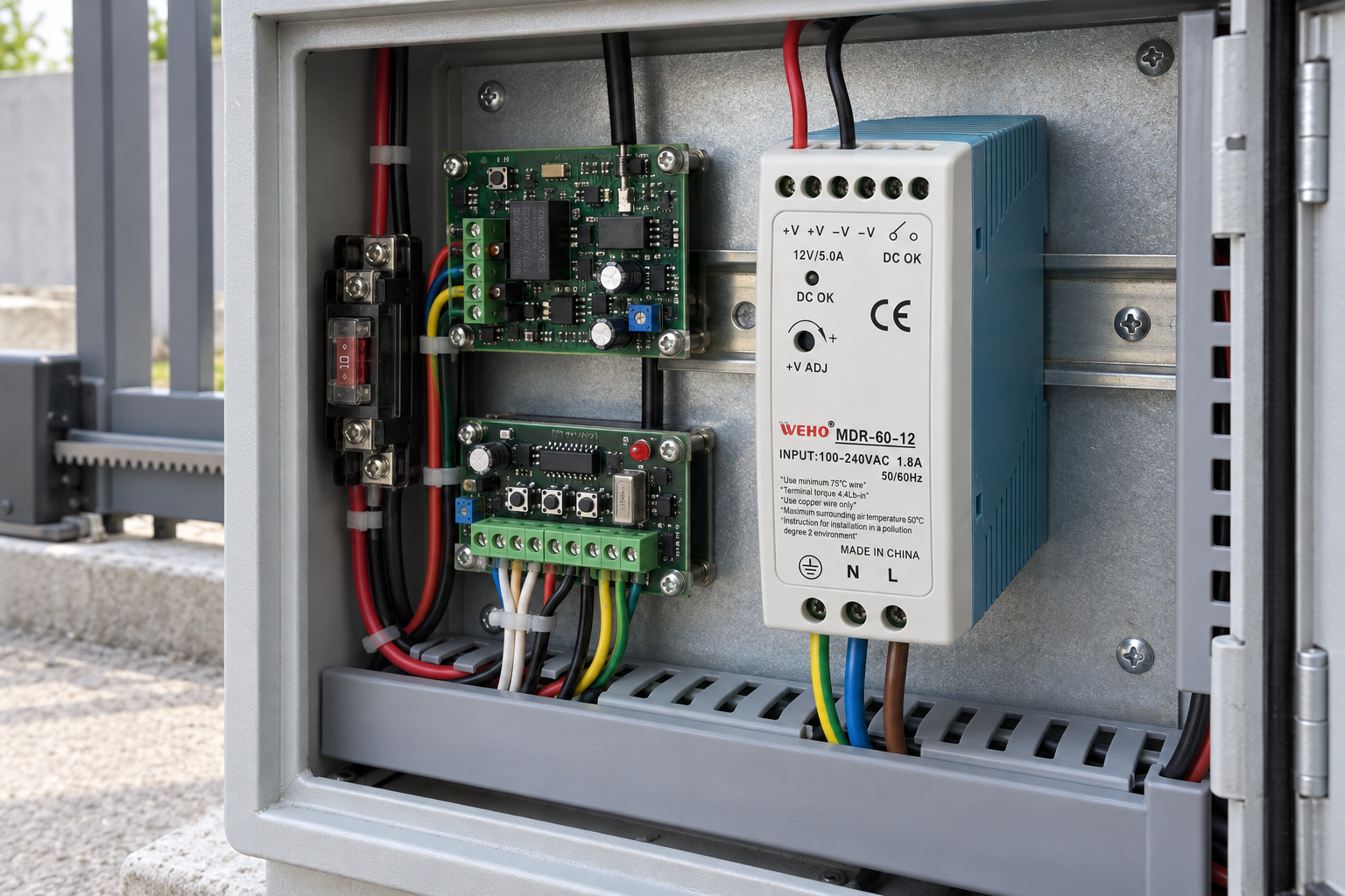
Retain the full MDR-60-12 identifier, original label, controlled specification, mounting drawing, receiver list and approved interface scheme in the equipment packet. A replacement review should address any changed supply variant, added accessory, different controller input or altered power-status logic. A familiar blue enclosure is not a sufficient like-for-like criterion.
Public and retained documents differ in some efficiency, adjustment and protection details. This draft does not select favourable values from those differences or promise outdoor, sealed-cabinet or unattended operation. Confirm the ordered revision and installation conditions with the manufacturer before release.
Can this supply power an unspecified barrier motor?
No such conclusion is supported. The article concerns an identified, compatible 12 V control branch, not the movement circuit.
Does DC OK replace a gate safety input?
No. It is a documented power-status contact whose integration still requires the equipment’s interface and safety design.
Send WEHO the exact controller requirements, branch load-state sheet and MDR-60-12 source records for configuration-specific confirmation.




