A 24V switching power supply installation needs a service record that preserves terminal protection after every approved change. The metal housing, terminal guard, equipment enclosure and harness each have a separate role. Changing a cover or moving a cable can alter access and cooling even when the supply part number stays the same.
This article addresses equipment already in production. The decision is which inspection or test evidence must reopen after a service-access change. It complements an initial replacement-compatibility checklist and an installed-space comparison; its output is a controlled change record.
On this page
Record the installed protection boundary
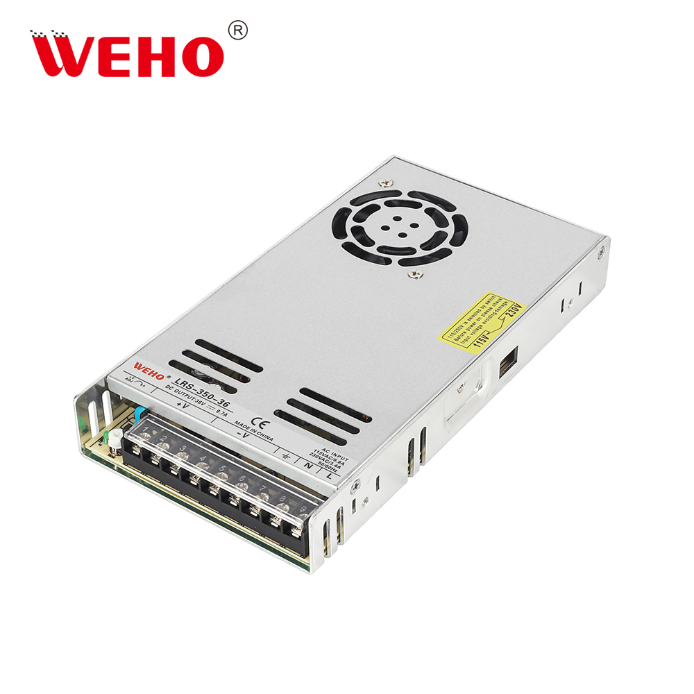
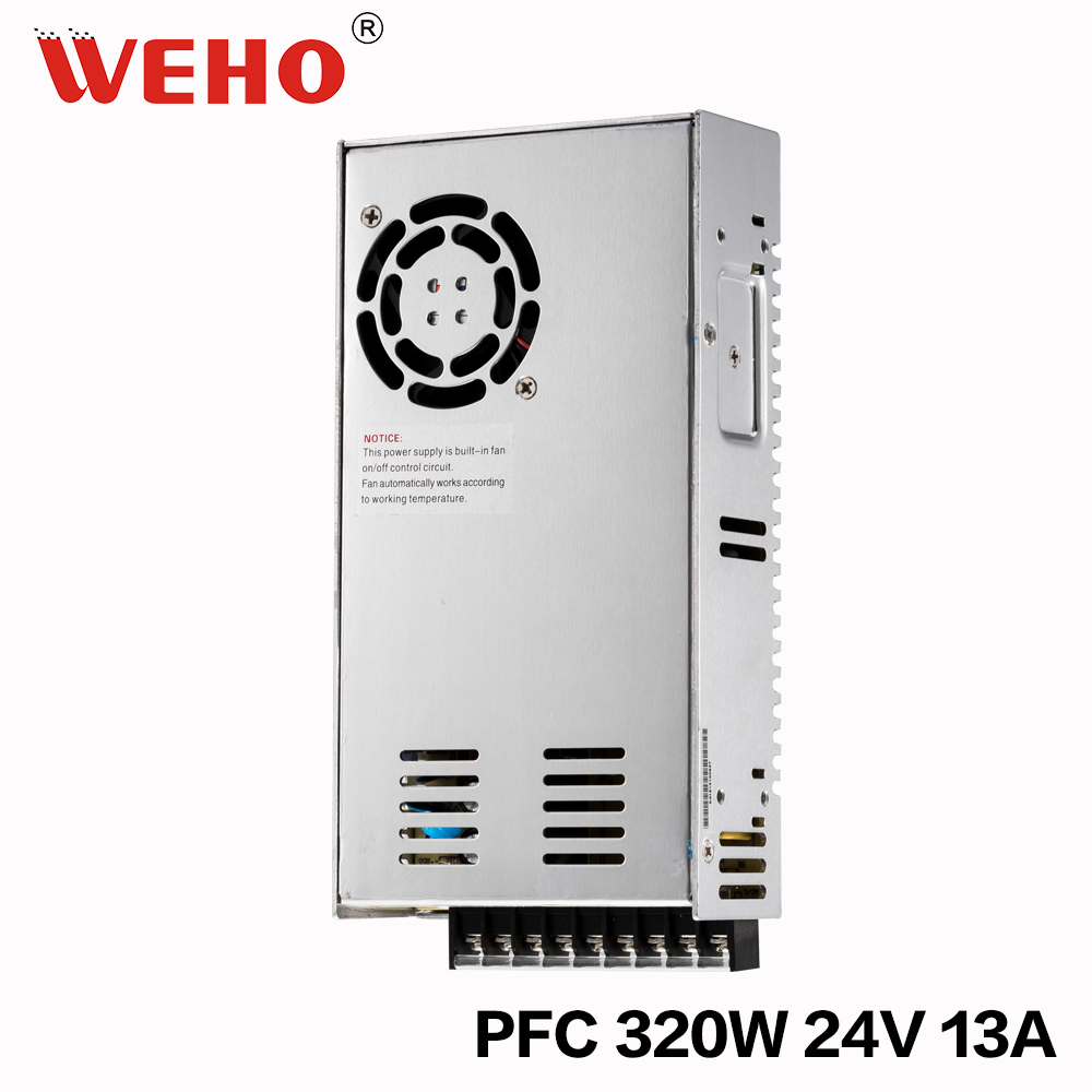
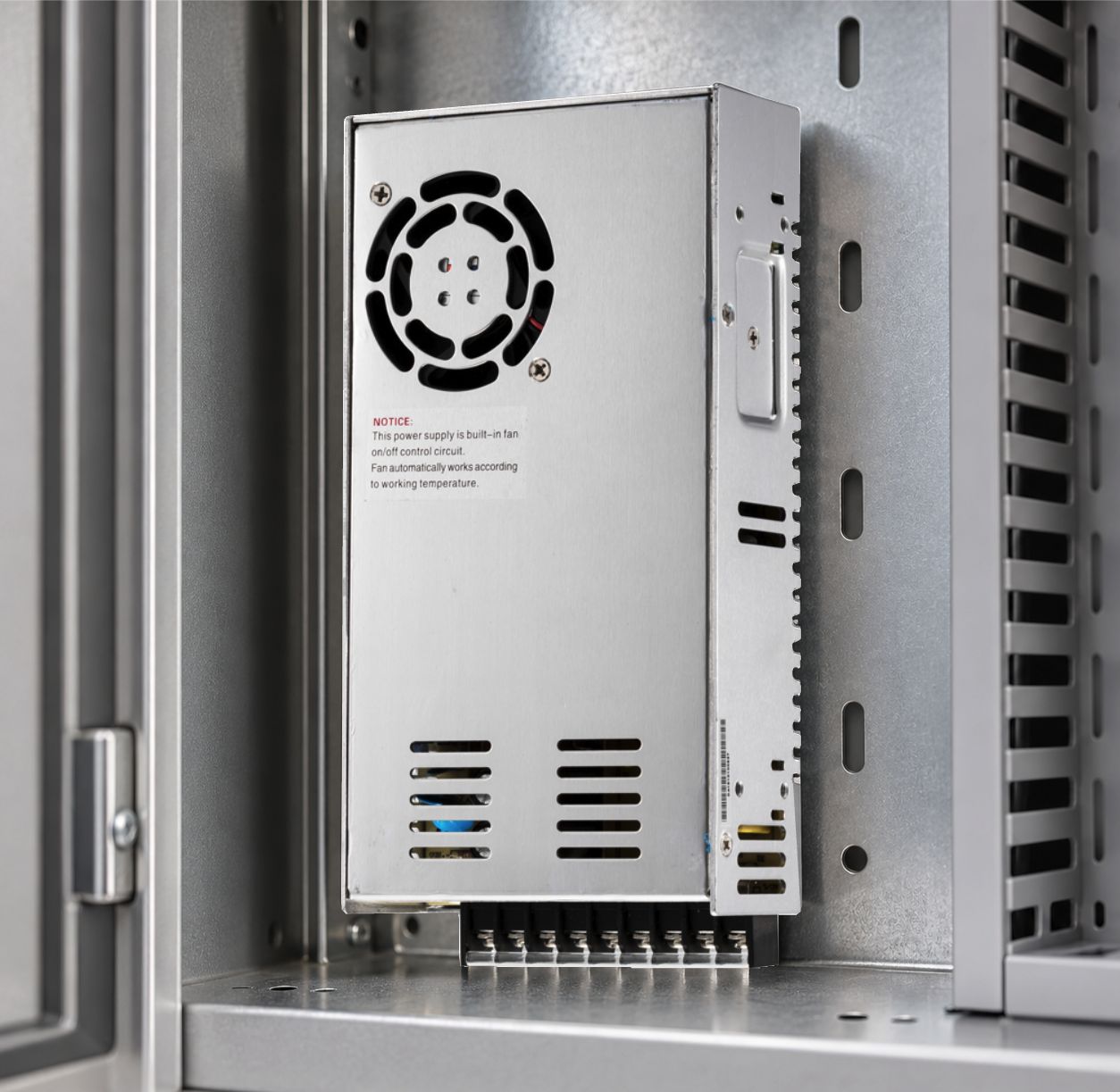
The WEHO LRS-350-36 product details and WEHO SP-320-24 product details identify two enclosed supply references for separate installations. The LRS photograph shows a clear cover over its terminal row; the SP photograph identifies a different terminal and cooling arrangement. Request the applicable installation drawing with the complete model suffix and revision.
Keep the electrical identities separate: LRS-350-36 is a 36 V reference, while SP-320-24 is a 24 V reference. Their placement here compares the records needed after a service change. It does not propose changing one supply for the other or transferring a cover, rating or installation instruction between them.
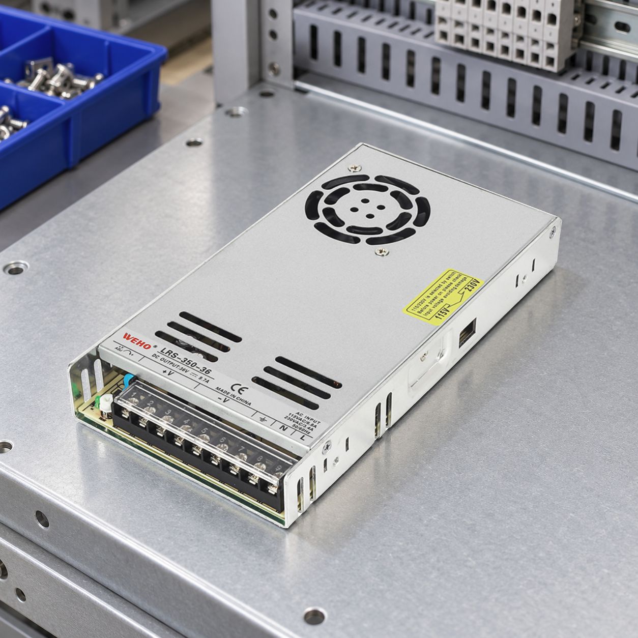
For each installed unit, record which barrier protects the terminal area in normal use and which parts service personnel remove. Include the guard or cover identity, retention method, surrounding equipment panels and the condition after reassembly. A visible plastic flap by itself does not establish the completed equipment’s access-protection rating.
Have qualified personnel follow the equipment’s isolation and stored-energy procedure before inspection. The review does not require defeating a barrier or exposing energized terminals. Identify every relevant energy source, including any separately supplied control or output circuit.
Freeze the service configuration, not just the housing
The baseline should show the actual assembly with conductors terminated, secured and routed. Record terminal assignments, applicable conductor preparation and tightening requirements from the exact instructions. Include any approved ferrules or lugs, insulation position and strain management. Do not copy torque or stripping values from a visually similar supply.
| Item changed | Reopen this question | Evidence to retain |
|---|---|---|
| Guard, flap or retaining screw | Does the specified barrier close and remain secured? | Accessory identity, fit inspection and applicable access assessment |
| Wire size, ferrule or cable entry | Are termination compatibility and insulation position preserved? | Exact terminal instruction and completed inspection |
| Harness restraint or service loop | Does movement pull on terminals or prevent closure? | Controlled route and de-energized service trial |
| Nearby panel or added shield | Does it alter cooling, bonding or required separation? | Updated drawing and affected thermal/electrical review |
Check the interaction between guarding and cooling
A service improvement can affect the power supply beyond tool access. An added shield may restrict a ventilation path. A cable tie may draw a bundle across a fan opening. For the SP-320-24 reference, record its pictured terminal area, fan opening and ventilation slots with the installed harness and guard. Review the specific change and the evidence it affects.
Hypothetical thermal calculation: an unrelated example supply delivers 24 V at 2 A, or 48 W, at an assumed efficiency of 90%. Estimated dissipation is 48 ÷ 0.90 − 48 = 5.33 W. A cover change can leave this dissipation unchanged while increasing the thermal resistance to surrounding air and therefore changing temperature rise.
Those assumptions are not measured LRS-350-36 or SP-320-24 data. The calculation explains why unchanged output current does not prove an unchanged thermal installation. Compare the revised assembly under its required load, input and local conditions with the applicable manufacturer limits and the original equipment record.
XP Power’s Essential Guide, Issue 3 explains how installed conditions affect thermal management. Use that general principle while obtaining WEHO’s exact model instructions; the guide’s model-specific examples do not set WEHO clearances or mounting requirements.
Work through one service-change example
Assume an OEM proposes a replacement terminal guard and a shorter harness on an existing assembly. Keep the supply model unchanged. First compare guard fit and retention with the controlled baseline. Then perform a de-energized removal/reassembly trial and inspect conductor approach, restraint and closure. A drawing comparison alone cannot show whether the technician must pull on a terminated wire.
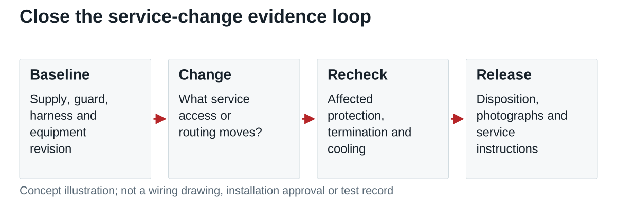
If the new guard crosses a ventilation opening, reopen the affected thermal assessment. If the harness route changes input/output separation or a bonding connection, ask the responsible engineer which electrical or EMC evidence needs updating. Retain the reason when evidence can carry forward; record an open action where confirmation is missing.
Release the change with a reproducible record
The release record should identify the supply, equipment revision, guard, harness and approved service sequence. Attach before/after photographs from the same useful viewpoints, the completed inspection, any repeated tests, and the disposition of each affected requirement. Update service instructions and spare-part identification together.
Send WEHO the exact model and proposed terminal-area change when requesting installation or accessory information. Include the existing and proposed configuration, required access and operating conditions. This gives engineering a concrete change to assess and purchasing a specific document set to request.