



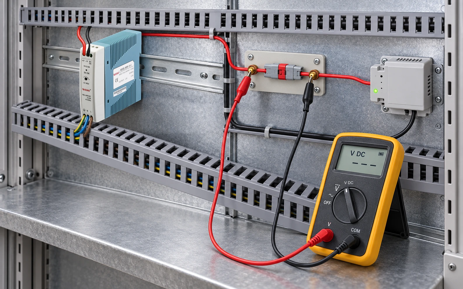
Measure a DC branch under a defined load before blaming the power supply or enlarging every cable. A poor connection can pass an unloaded voltage check yet create a localized drop and heating when current flows. Separate source behavior, conductor loss and individual contact loss.
This method is intended for OEM maintenance and acceptance teams reviewing a small 5 V branch with an MDR-10-5 as the identified source. It does not authorize working on exposed mains or prescribe a torque value.
Define the two measurements and the operating state
Record the source output voltage and receiver input voltage during the same stable state. Document meter accuracy, measurement locations, current and receiver behavior. An unloaded reading at the supply terminals does not describe the voltage at an operating receiver.
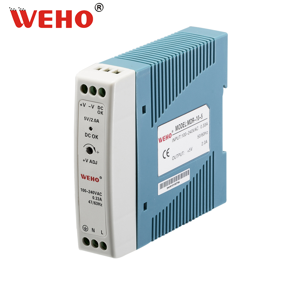
The MDR-10 product page identifies the compact family. The original visible MDR-10-5 marking is retained as product identity. Use the exact supplied unit’s limits when defining an approved load test; the small family name is not permission to apply an arbitrary diagnostic load.
Estimate the complete path loss before localizing it
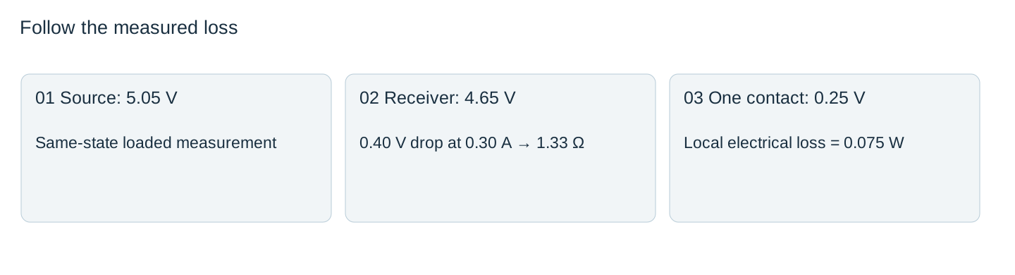
Suppose an authorized test records 5.05 V across the source output terminals, 4.65 V across the receiver input terminals and 0.30 A through the branch. The hypothetical round-trip path loss is 0.40 V, and its equivalent total loop resistance is R = ΔV/I = 1.33 Ω. This includes the positive conductor, return conductor and intervening contacts or series elements, not just one length of copper wire.
Compare that result with the documented cable length, cross-section, temperature and connector arrangement. If the cable estimate accounts for only part of the drop, investigate the remaining contacts and paths. Meter uncertainty and non-simultaneous readings may matter when the drop is small or the load varies.
Localize a loss without confusing it with the source
| Observation under the same state | Possible review direction | Evidence still required |
|---|---|---|
| Source stable; receiver lower | Distribution path | Segment voltage drops and current |
| Both source and receiver fall | Source/input/load interaction | Input condition and supply operating limits |
| One connection has disproportionate drop | Local contact or termination | Approved inspection and connection instructions |
| Result changes with motion or heat | Intermittent interface | Controlled, authorized repeatability test |
These observations guide investigation; they do not diagnose a failed component by themselves. A localized drop can be caused by an incorrect crimp, damaged contact, contamination or an unsuitable mating combination. Document what is actually found.
Convert an observed local drop into a loss estimate
If 0.25 V of the example drop occurs across one connection at 0.30 A, its electrical loss is P = IΔV = 0.075 W. This is a local heat input. It is not a predicted contact temperature, and there is no universal acceptable temperature rise derived from this number alone.
Phoenix Contact’s connector data illustrates that allowed current depends on the specified contact and conductor conditions. It does not supply ratings for the unidentified connection in this example. Use the actual terminal or connector instructions for inspection and rework.
Do not tighten a powered connection as an exploratory test. Perform any physical intervention under the approved isolation and verification procedure, then repeat the same loaded measurement after documented rework.
Close the record with a cause and a repeat measurement
Retain before-and-after values, the actual defect, repair method and current hardware revision. Confirm that the receiver voltage meets its stated limit across the intended states. A reduced drop at one state is not proof that every intermittent or thermal condition has disappeared.
If the connection is sound and the cable accounts for the loss, revise the branch design using a voltage budget. If the source itself leaves its permitted range, investigate its operating point separately. Keeping those decisions distinct prevents a good supply being replaced while a bad termination remains in service.
Share the MDR-10-5 branch record with source and receiver voltages from the same loaded state, current, segment drops, connection identities and before-and-after findings. Request the supplied revision’s limits if the source itself is suspect; use the documented contact or cable evidence to resolve the distribution fault.
Loaded branch loss investigation
| State/current | Source voltage | Receiver voltage | Segment/contact loss | Finding and action |
|---|---|---|---|---|
Blank project worksheet. Enter verified project data; example calculations above are not measurements.



