



Release a Q-120B service harness only when the voltage assignment, connector orientation and wrong-mate prevention agree. The B variant has +5 V, +12 V, −5 V and −12 V outputs. A wire list alone does not show whether a replacement harness can be reversed, inserted into a nearby socket or supplied under the wrong part number.
This guide is for an OEM building a serviceable instrument with four supply rails. Its output is a harness verification record linking the exact supply variant to the receiver’s approved pins. It does not establish the receiver’s load compatibility or the supply’s performance under uneven loading; those remain separate design checks.
Start with the B variant and signed rail names
The WEHO Q-120 product table identifies the Q-120B combination as +5 V, +12 V, −5 V and −12 V. The official Q-120 specification sheet also distinguishes B from the +15 V/−15 V C variant. Some family photographs show a different output combination. Use the exact model table and the received unit’s approved marking, not the appearance of a shared enclosure.
Create the electrical interface record before assigning connector cavities. Give each conductor a rail name, its reference and a destination. A “12 V” annotation without a sign is inadequate where both +12 V and −12 V exist. Likewise, a voltage measured between two non-COM rails is not the same as either rail’s voltage relative to COM.
| Circuit identity | Required record | Do not infer |
|---|---|---|
| +5 V, +12 V, −5 V, −12 V | Signed nominal voltage; approved receiver range; reference. | That two opposite signs can be exchanged. |
| COM | Specific intended return path and receiver reference. | That COM and protective earth are interchangeable. |
| Supply and receiver interface | Exact drawing revisions and actual terminal markings. | A terminal order from another Q-family photograph. |
Make the connector view impossible to misread
For every plug and receptacle, identify the connector manufacturer’s part number, cavity numbers, key or polarization option, contact type and the view used in the drawing. State “mating face” or “wire-entry face,” with a fixed datum such as the latch at the top. A mirrored view can produce an internally consistent harness drawing that is wrong at the receiver.
Use wire identifiers that remain legible after assembly. Color can help technicians find a conductor, but the controlled cavity and circuit records must survive a color substitution. Include any splices, shared returns and unused cavities in the drawing so that an unrecorded change cannot hide inside a bundle.
Check contact and wire suitability separately. Mechanical fit does not establish current rating, temperature performance, crimp acceptance or mating-cycle capability. Those must come from the selected connector system and its application specification, not from the Q-120B output table.
Review the unwanted connection, not only the correct one
Molex’s connector mating guidance distinguishes polarization, which controls orientation within a pair, from keying, which separates similar interfaces. Visual coding can identify a function without physically preventing an incorrect connection. Apply that distinction to the actual service task: two differently colored plugs may still fit the same socket.
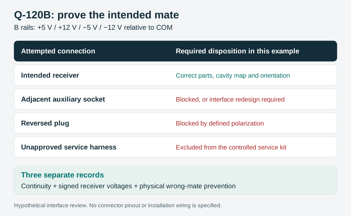
The matrix below is a hypothetical review example, not a proposed Q-120B connector pinout. Each unwanted pairing needs a physical or procedural disposition before the harness is released. Inspect actual parts without power and without forcing an incompatible connector.
| Attempted pairing | Required disposition in the example | Evidence recorded |
|---|---|---|
| Four-rail harness → intended receiver | Fits in the documented orientation. | Correct part numbers, cavity map and latch engagement. |
| Four-rail harness → adjacent auxiliary socket | Mechanically blocked, or redesign required. | Actual keying comparison and unpowered inspection. |
| Four-rail harness → intended receiver reversed | Blocked by the selected polarization. | Drawing view and physical orientation check. |
| Unapproved replacement harness → receiver | Held outside the approved service kit. | Controlled service part and substitution review. |
A label alone may be a necessary instruction, but do not record it as a mechanical barrier. If a plausible incorrect mate remains possible, change the interface or document an engineering decision with the equipment’s risk assessment. This article does not claim a universal connector solution for every instrument.
Perform continuity and signed-voltage checks in separate stages
First verify the isolated, unpowered harness against its controlled cavity map. Record intended continuity and unwanted shorts using a method suitable for the cable and disconnected equipment. Keep the receiver isolated where required; do not apply a cable test voltage to electronic inputs without their manufacturer’s approval.
Then use the equipment’s approved commissioning procedure to verify signed voltages at the receiving interface before exposing the receiver to an unverified harness. A qualified person must control access to the supply’s AC terminals. Use the intended reference, appropriate instruments and any necessary test loads specified for the supply. Do not treat a four-rail no-load reading as proof of loaded regulation.
Record the connector cavity, reference cavity, sign and measured value for each rail. “Continuity passed” and “+12 V present” answer different questions. Neither establishes that an incompatible neighboring socket is physically blocked; keep that check visible as a third result.
Keep the approved service kit aligned with production
The released kit should identify the harness revision, both mating connector parts, keying variants, contact specification and assembly inspection record. If the harness can be sourced from two suppliers, compare the same interface evidence rather than accepting “equivalent four-rail cable” as a complete description.
Reopen the review after a receiver-board revision, connector substitution, repinning, supply-suffix change or a new adjacent service port. A retained housing with a changed cavity assignment can defeat the original error-prevention design even though it still latches correctly.
Use the worksheet to leave a traceable result for the technician and purchasing team. The useful release statement is specific: this harness revision, this Q-120B configuration and this receiver interface were checked against the attached records. It should not imply that every Q-120 family variant or future replacement is interchangeable.
Use the project record
Open the blank Q-120B harness and unwanted-mating release record to record your conditions, evidence and decisions. The worksheet contains no pre-approved result.
When enquiring about the Q-120B four-output supply, request the exact output and terminal information for the intended revision. Combine it with the receiver and connector documentation before releasing the service harness.




