



Key Engineering Takeaways
- Welding-field immunity and resistance to hot spatter are different qualification questions.
- A metal housing or an ingress rating does not establish either welding capability.
- Evaluate required present and absent states during the relevant welding sequence, not only with welding off.
- Use ordinary LJA18 family imagery for identification; obtain actual configuration evidence before selection.
1. Define the welding exposure before approving a sensor
A sensor that detects a fixture flag with welding off still needs evidence for its intended welding environment. Electromagnetic interference, hot spatter and accumulated debris can affect an installation through different mechanisms. Approval should identify the exposure and required output behavior, rather than rely on a general description such as “rugged industrial sensor.”
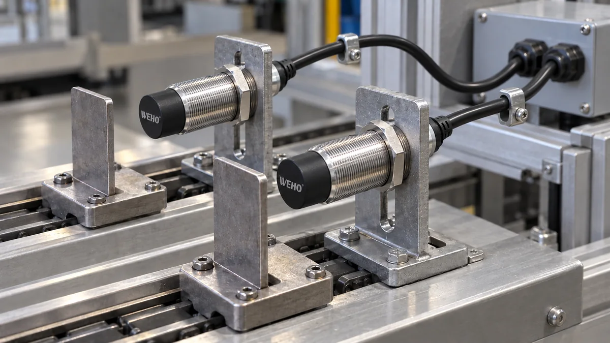
The WEHO LJA18 inductive proximity switch family provides the ordinary sensor identity for this qualification discussion. The family photograph and a successful routine metal-target check do not establish welding-field immunity, spatter resistance or a suitable cable construction. The full ordered configuration and application evidence are necessary before a welding-cell recommendation.
2. Keep magnetic interference and material damage separate
Welding currents can produce electromagnetic conditions that disturb sensor operation, while hot spatter can accumulate on or damage faces, bodies and cables. Balluff's welding guidance treats these as separate selection concerns, together with heat, mechanical impact and installation constraints. The distinction supports an exposure-based inquiry, not transferring Balluff product capabilities to another sensor. Balluff welding-sensor selection guide
An appropriate field-immunity statement needs conditions and product identity. A claim for a special design does not automatically cover every current waveform, conductor arrangement or sensor orientation at a site. OMRON publishes welding-specific proximity-sensor specifications for identified models, demonstrating that welding suitability is documented at a product and condition level. OMRON E2EW welding-sensor specifications
Spatter resistance requires separate material and maintenance evidence. A housing may remain electrically functional during a short pulse while the sensing face, connector or cable is progressively damaged over repeated exposure. Conversely, a suitable protective material does not prove immunity to the electromagnetic field. Keep both questions open until the actual assembly has supporting evidence.
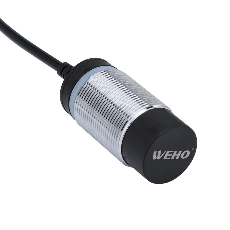
Specialized manufacturer documentation distinguishes coatings and face protection from weld-field immunity. Those features illustrate different engineering responses to different exposures; their published values belong to the identified specialty products. Do not infer either capability from the LJA18 family's ordinary metal housing or the appearance of its product photograph. Balluff welding-environment catalog
3. Construct an explicit hypothetical coverage matrix
Consider an assumed fixture qualification plan with two required target states: a metal flag present and the flag absent. For each state, examine three exposure windows: welding off, the authorized welding sequence and the period immediately afterward. Repeat those conditions in an initial assembly state and after representative accumulated thermal exposure.
The plan contains 2 target states × 3 exposure windows × 2 thermal states = 12 distinct condition cells. If the example planner chooses three documented repeats per cell, the plan contains 36 observations. The repeat count is an illustration, not a statistical reliability claim, a test standard or a WEHO qualification requirement.
| Exposure window | Flag present | Flag absent | Record in each thermal state |
|---|---|---|---|
| Welding off | Verify required detection | Verify required reset | Baseline output and fixture state |
| Authorized welding sequence | Observe required state throughout window | Observe required state throughout window | Output with synchronized welding event |
| Immediately after sequence | Verify required recovery behavior | Verify required recovery behavior | Transient state, persistence and timing |
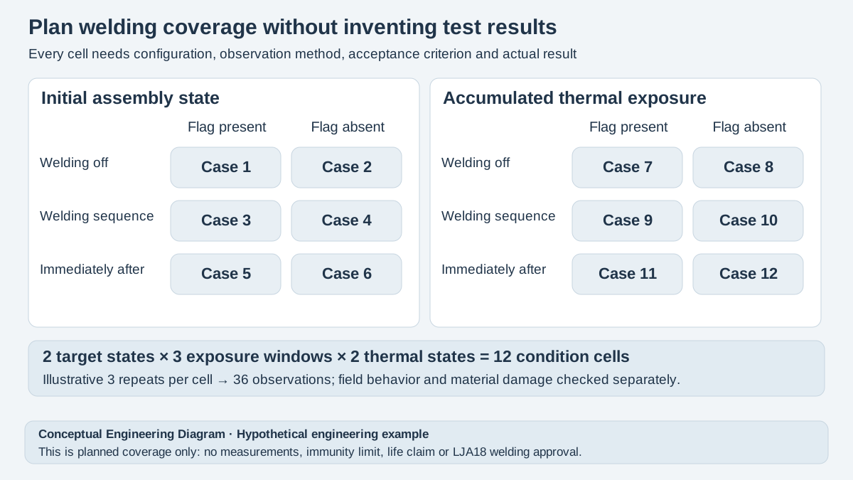
Swipe horizontally on a small screen, or open the full-size diagram.
The matrix describes planned coverage, not completed results. Each actual cell needs a configuration identifier, exposure record, observation method, acceptance criterion and result. An unobserved interval should remain unverified. A slow status display may miss a transient, so record the receiving-system observation method and its limitations rather than equating a steady indicator with uninterrupted correct operation.
For the example, the engineering team could require no unintended logical transitions within each defined observation window. That criterion must still be tied to the machine's required behavior and measurement capability. Thirty-six observations satisfying a criterion would support that recorded trial; they would not establish a lifetime failure rate or cover a different welding program.
4. Request evidence for the complete assembly
A practical supplier package identifies welding process, approved current program, pulse or duty information, conductor and return paths, sensor location and orientation. Include nearby welding cables and actual mounting drawings. A distance to the weld alone leaves important geometry unspecified, while a photograph without dimensions may conceal a cable route that changes between machine variants.
| Qualification issue | Evidence needed | Insufficient substitute | Decision if unresolved |
|---|---|---|---|
| Electromagnetic exposure | Applicable immunity evidence and site event record | Metal housing or generic industrial wording | Hold welding-field approval |
| Spatter exposure | Face, body, cable and connector compatibility | Field-immunity statement alone | Revise protection or obtain qualified assembly |
| Çalışma sıcaklığı | Actual exposure and assembly limits | Short room-temperature check | Extend representative evaluation |
| Maintenance condition | Allowed cleaning and inspection criteria | Appearance after one clean cycle | Define service boundary before release |
Ordinary environmental or ingress documentation remains useful within its stated scope, but does not answer these welding-specific questions. Preserve the exact title and conditions of every report rather than reducing several documents to one “certified” checkbox. If a supplier cannot connect the evidence to the ordered assembly, record the qualification gap explicitly.
A shield or relocated bracket can change the sensing environment as well as exposure. Nearby metal can affect inductive detection, and a changed mounting arrangement therefore requires renewed functional evaluation. Follow the actual model's installation information and retain the revised drawing. OMRON general proximity-sensor installation precautions
5. Execute and retain a bounded qualification record
- Identify the sensor assembly. Record complete code, sensing-face material, cable, connector and protection accessories. Verify that claimed welding and environmental evidence applies to that configuration rather than a related specialty model.
- Map the authorized welding exposure. Record the approved process program, relevant current information, conductor routes and sensor position. Verify that the proposed trial represents the intended machine envelope without altering welding or safeguarding procedures.
- Define observation windows and states. Record the required present/absent behavior and capture method for every matrix cell. Verify that the observation interval can reveal transitions relevant to the receiving equipment.
- Run the approved sequence and inspect. Record actual outputs, exposure conditions and before/after assembly condition using the equipment's controlled procedure. Verify field behavior separately from spatter accumulation, material damage and cable condition.
- Close gaps and freeze the configuration. Record failures, missing cells, protection revisions and supplier responses. Verify the revised installation before release, with a defined maintenance boundary and changes that trigger requalification.
Do not hide unexplained transitions by removing them from the record or adding undocumented signal blanking. If the machine intentionally disregards a sensor during part of the cycle, the controls engineer must define that interval and its consequences. Such a design decision changes the information available to the machine; it does not prove continuous sensor immunity.
Keep personnel-protection functions outside assumptions about an ordinary presence sensor. The sensor qualification discussed here concerns a defined process-detection task. Any protective function needs its own documented architecture and applicable components, with the machine's approved procedures governing access, testing and operation.
6. Send WEHO the welding-specific evidence request
Send WEHO the exact LJA18 family inquiry and ordered-code information, target and mounting drawings, approved welding exposure summary and the proposed observation matrix. State explicitly that welding-field immunity and spatter compatibility require confirmation. The ordinary application photo demonstrates neither a welding installation nor a completed qualification.
The next action is to obtain applicable assembly evidence, agree on a representative authorized trial and document unresolved conditions. Approve only the recorded process and installation, then revisit the decision after welding-program, conductor-route, protection, cleaning or sensor-configuration changes.
7. Frequently asked questions
Does a metal housing prove that an inductive sensor is weld-field immune?
No, a metal housing does not establish weld-field immunity. Obtain a configuration-specific statement with applicable conditions, then verify the installed behavior under the intended authorized welding sequence.
Is weld-field immunity the same as resistance to hot spatter?
No, weld-field immunity addresses electromagnetic behavior, while spatter resistance addresses a different physical exposure. Review the sensing face, body, cable, connector and maintenance requirements separately.
Can a test with welding switched off approve the whole application?
No, a welding-off check establishes only the recorded baseline detection behavior. Evaluate the relevant welding and recovery windows, thermal states and accumulated material exposure before closing the application qualification.
Do thirty-six example observations establish a reliability rating?
No, the thirty-six observations are an illustrative coverage plan rather than a reliability demonstration. Actual repeat counts, observation methods, acceptance criteria and confidence requirements must be defined for the intended engineering decision.



