...

Product Categories

LRS-100 Series 100W Single Output Enclosed Switching Power Supply (LRS-100-12 / LRS-100-24)

Single-Output Versions: LRS-100-12, LRS-100-15, LRS-100-24 and LRS-100-48 provide 12V, 15V, 24V and 48V. Listed current ranges are 0~8.5A, 0~7A, 0~4.5A and 0~2.3A respectively.

Efficiency by Version: 86%, 88%, 88% and 90% in the same voltage order.

Input and Size: 85~264VAC or 120~373VDC, 47~63Hz; 129×97×30mm enclosure.

اگر آپ کے کوئی سوالات ہیں تو، براہ کرم ہم سے رابطہ کرنے میں سنکوچ نہ کریں۔ ای میل: [email protected]

Overview

The LRS-100 is a single-output AC/DC power supply. It is a candidate for the interface and sensing electronics of small production machines, identification stations and enclosed instruments. The specified overall dimensions are 129 × 97 × 30 mm. Output selection and physical fit can be checked independently, keeping accessory-power design distinct from the machine process. Use the equipment input specification and measured demand to select the variant.

Why Choose LRS-100?

Reserve the physical envelope

The specified overall dimensions are 129 × 97 × 30 mm. A fixed envelope is useful for identification benches and compact machine bases where the process fixtures also need access.

Select by electronics input

The LRS-100 offers separate 12 V, 15 V, 24 V and 48 V models: LRS-100-12, LRS-100-15, LRS-100-24 and LRS-100-48, respectively. Selecting the correct variant avoids assuming that a single unit supplies every auxiliary rail used in the equipment.

Keep regulation categories clear

Line regulation and load regulation are each listed as ±0.5%. The separate figures help compare steady-state behavior without inventing an overall accuracy figure.

Include startup in the design review

The listed cold-start current is 50 A at 230 VAC. The specified cold-start figure flags an upstream switching consideration that the normal DC load current does not capture.

Features, Benefits & Advantages

فیچر Benefit in equipment design
Voltage-specific noise values The listed ripple-and-noise values are 120 mVp-p, 120 mVp-p, 150 mVp-p and 200 mVp-p for LRS-100-12, LRS-100-15, LRS-100-24 and LRS-100-48, respectively. The separate values are useful when screening a camera or signal-interface rail for further noise testing.
Variant-specific efficiency The listed efficiencies are 86%, 88%, 88% and 90% for LRS-100-12, LRS-100-15, LRS-100-24 and LRS-100-48, respectively. Use the relevant value for preliminary loss estimation rather than assigning the best figure to every output.
Adjustment around the selected rail The DC-voltage adjustment range is listed as ±10%. Verify the final setting at the equipment input after distribution losses are considered.
Cutoff and automatic recovery Overload protection cuts off the output at 110%–150% and provides automatic recovery. The sheet also lists overcurrent protection and short-circuit protection. Evaluate branch faults and system restart separately from normal electronics demand.
تفصیلات LRS-100-12 LRS-100-15 LRS-100-24 LRS-100-48
ڈی سی آؤٹ پٹ وولٹیج، کرنٹ 12V 0~8.5A 15V 0~7A 24V 0~4.5A 48V 0~2.3A
لہر اور شور 120mVp-p 120mVp-p 150mVp-p 200mVp-p
inlet تار استحکام ±0.5% ±0.5% ±0.5% ±0.5%
لوڈ استحکام ±0.5% ±0.5% ±0.5% ±0.5%
کارکردگی 86% 88% 88% 90%
ڈی سی وولٹیج کے لیے سایڈست رینج ±10% ±10% ±10% ±10%
ان پٹ وولٹیج کی حد 85~264VAC / 120~373VDC, 47~63Hz
اثر کرنٹ کولڈ اسٹارٹ موجودہ 50A/230VAC
اوورلوڈ تحفظ 110%~150% آؤٹ پٹ، خودکار بحالی
دیگر تحفظ Overcurrent protection /Short-circuit protection
Timing (setup / rise / hold-up) 230VAC: 500ms, 30ms; 115VAC: 500ms, 30ms. No separate hold-up time is specified.
وولٹیج کا مقابلہ کریں۔ I/P-O/P:1.5kV I/P-FG:1.5kV O/P-FG:0.5kV 1 منٹ
تنہائی کی مزاحمت I/P-O/P I/P-FG O/P-FG:100M Ohms/500VDC/25℃ /70%RH
کام کرنے کا درجہ حرارت -20℃~+70℃
طول و عرض 129 × 97 × 30 ملی میٹر
وزن 0.34 کلوگرام
پیکنگ 42.5×32.5×19.5CM/45PCS/16kg

Mechanical dimensions

LRS-100 — dimensions in millimetres
Body length129 mm
Body width97 mm
Body height30 mm

The body dimensions and mounting-hole dimensions are different references. The vector drawing below retains the dimensions printed in the WEHO original.

On a small screen, swipe the drawing horizontally to inspect every dimension. No separate drawing image or script download is required.

Exact mechanical drawing from the WEHO original. Units: mm. Use the printed body, mounting and hole dimensions separately.

Load derating

Apply these model-specific curves only within the stated WEHO operating range of -20 to +70 °C and the input range in the specification table. A reference axis extending below that range does not extend the product rating. Follow the input-voltage and mounting-orientation labels shown on each curve.

Native technical vectors from the owner-adopted same-model reference. All source input, output and installation conditions remain applicable; do not extrapolate beyond the WEHO stated limits.
Permitted load versus ambient temperature. Observe the separate input-voltage curves where shown.
Native technical vectors from the owner-adopted same-model reference. All source input, output and installation conditions remain applicable; do not extrapolate beyond the WEHO stated limits.
Permitted load versus AC input voltage at the frequency shown. Use the correct input selector setting where applicable.
View the functional block diagram Native technical vectors from the owner-adopted same-model reference. All source input, output and installation conditions remain applicable; do not extrapolate beyond the WEHO stated limits.

Typical Service Conditions

AI LRS-series planning and application illustrations; equipment scenes are not customer-installation records or exact-model dimensional or wiring evidence.


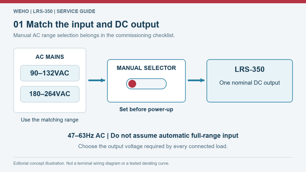
Select 90–132VAC or 180–264VAC manually before energizing, then verify the chosen DC output and polarity.

Input matching: LRS-100 versus the selector example

The illustration shows the LRS-350 manual-range example; do not transfer its 90–132/180–264 VAC bands to LRS-100. The input specification lists 85–264 VAC / 120–373 VDC and 47–63 Hz. The input range does not document a selector switch or an automatic range-switching mechanism. Match the selected DC version to every connected input, then include simultaneous demand and startup transients before energising the equipment. The planning image is a representative LRS-series example, not an exact-model wiring diagram.

LRS-350 manual-selector planning example; use LRS-100 input bands, selection instructions and output options, not the example labels.


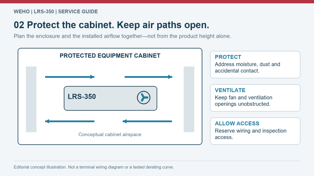
Keep fan and ventilation openings unobstructed inside a cabinet selected for the actual environment. Arrows show conceptual airspace, not a measured airflow path.

LRS-100 enclosure and service-space planning

The specified overall dimensions are 129 × 97 × 30 mm. The listed product weight is 0.34 kg. Reserve additional space for terminal access, conductor routing and the host equipment's airflow; the case outline is not a clearance allowance.

LRS-series cabinet-space concept; the exact case, cooling method and mounting are defined by this model's own technical data.


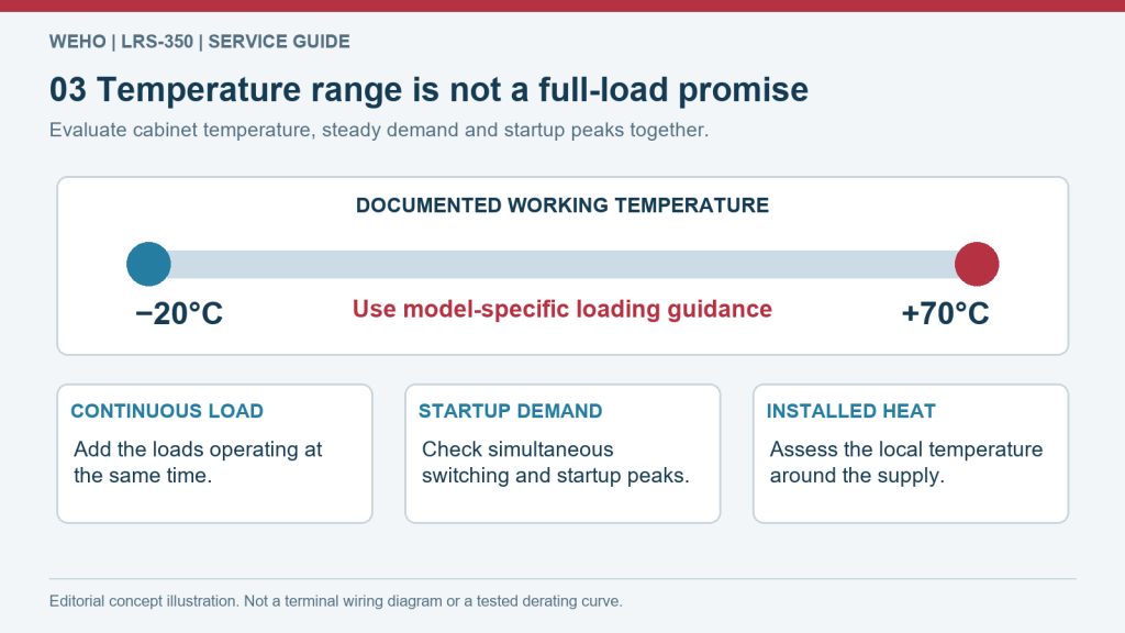
The −20°C to +70°C working range does not establish full output at every temperature. Use the selected version’s load and thermal limits.

Temperature and duty-cycle assessment for LRS-100

The specified working-temperature range is -20°C to +70°C. Use the temperature/load curve displayed with the model-specific technical data under its stated conditions. Measure the temperature at the installed supply and review the longest expected duty cycle. Keep vents unobstructed; do not substitute room temperature for the operating temperature inside the equipment.

LRS-350 temperature-planning example, not a measured derating curve or a replacement for LRS-100 operating limits.


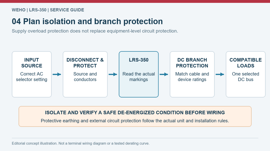
Functional power-planning illustration only. Have qualified personnel select protection, follow terminal markings and verify safe isolation before work.

LRS-100 fault recovery and protected installation

Overload protection cuts off the output at 110%–150% and provides automatic recovery. The sheet also lists overcurrent protection and short-circuit protection. Have a qualified installer check terminal identification, protective earthing and branch protection for the actual assembly. Coordinate restart behaviour with the equipment controls rather than treating supply recovery as a safety function.

Functional power-planning illustration only; follow the exact model's terminal identification and qualified installation instructions.


Application Industries

AI LRS-series planning and application illustrations; equipment scenes are not customer-installation records or exact-model dimensional or wiring evidence.


AI illustration of an illuminated retail lightbox and storefront at blue hour.

Retail sign-control and LED-module branches

For a backlit retail panel, evaluate LRS-100 against one documented constant-voltage module group and its control interface. Verify the modules accept the selected DC setting and provide current control where required. Reserve the rest of the store lighting for its own power design.

The LRS-100-12 column lists 12 V and an output-current range of 0–8.5 A.

AI application concept — retail signage, not an installation record for this product.


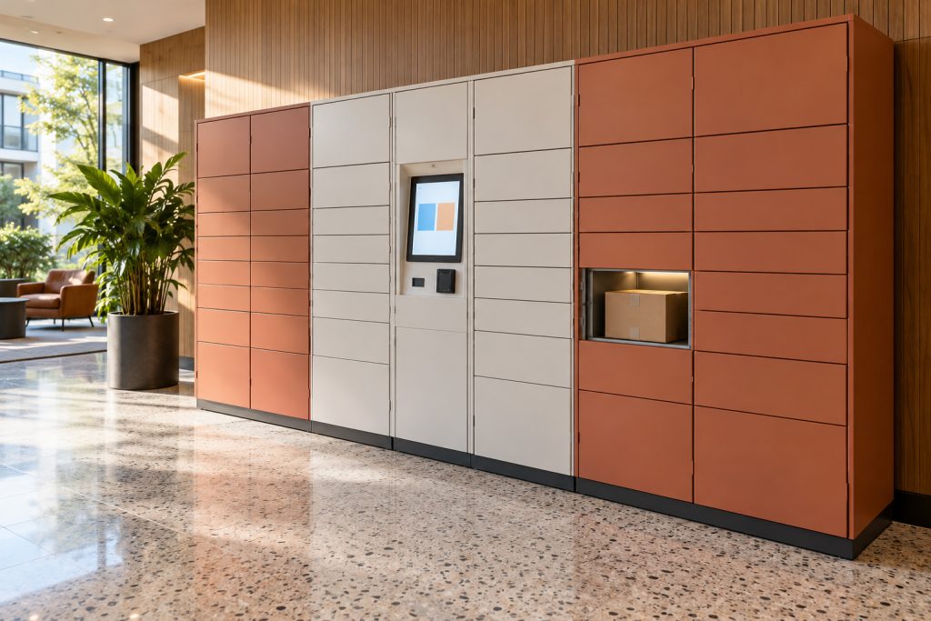
AI illustration of complete self-service parcel lockers and a central pickup screen in a bright indoor lobby.

Parcel-terminal interface electronics

A parcel pickup station may group its controller, sensors and selected lock interfaces on compatible protected DC branches. Check the LRS-100 version against the actual release sequence and peripheral startup, not a whole-terminal wattage estimate. No redundancy or UPS function is assumed.

The LRS-100-24 column lists 24 V and an output-current range of 0–4.5 A.

AI application concept — parcel-terminal electronics, not an installation record for this product.


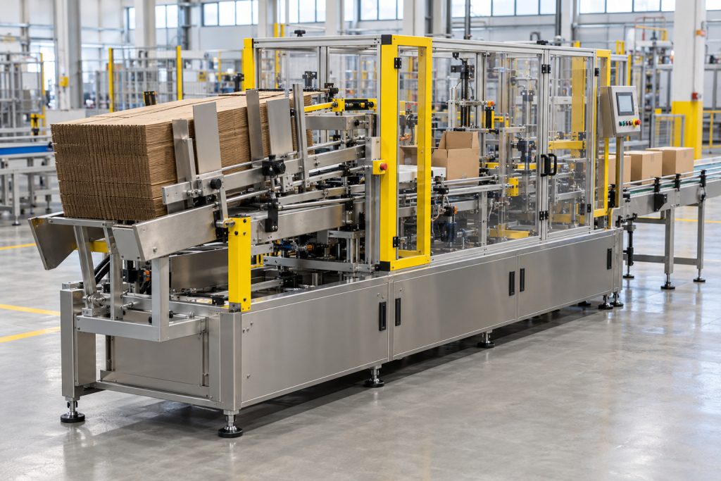
AI illustration of a complete guarded automatic carton-packing machine on a production floor.

Carton-packaging auxiliary electronics

Consider LRS-100 for the sensing and interface side of a carton-forming machine, including compatible position detection and operator-status electronics. Coordinate branch suppression and controller restart after an output interruption. Motion, sealing heaters and safety functions are assessed independently.

The LRS-100-15 column lists 15 V and an output-current range of 0–7 A.

AI application concept — carton-packaging auxiliary electronics, not a complete-machine power claim.


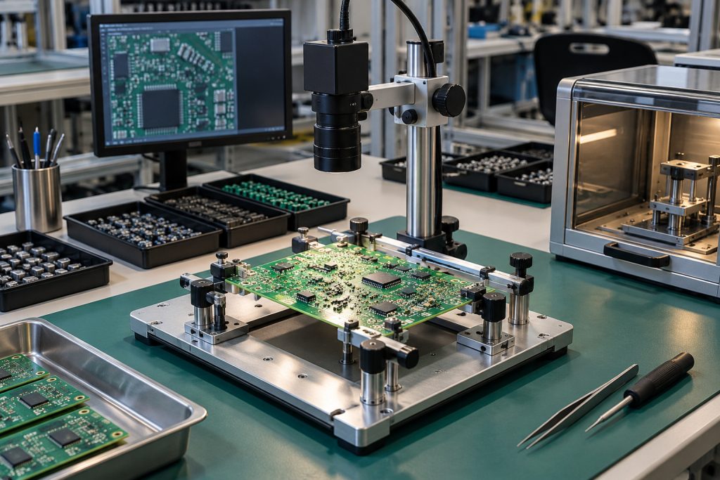
AI illustration of an electronics inspection workbench with a supported PCB fixture and optical inspection equipment.

Electronics-fixture auxiliary interfaces

At the pictured electronics station, a compatible LRS-100 rail can support fixture actuation interfaces and inspection-control electronics. Check any camera, illumination controller and converter individually. Precision excitation and noise-sensitive measurements require a suitable dedicated source or conditioning.

The LRS-100-48 column lists 48 V and an output-current range of 0–2.3 A.

AI application concept — electronics-fixture interfaces; no measurement-performance or installed-model claim.


Frequently Asked Questions

Which output-voltage models does the LRS-100 provide?

The LRS-100 offers separate 12 V, 15 V, 24 V and 48 V models: LRS-100-12, LRS-100-15, LRS-100-24 and LRS-100-48, respectively. Each model is a single-output choice; the alternatives are not simultaneous rails on the same unit.

How are the LRS-100 current ranges and series-power statement distinguished?

The printed output-current ranges are 0–8.5 A, 0–7 A, 0–4.5 A and 0–2.3 A for LRS-100-12, LRS-100-15, LRS-100-24 and LRS-100-48, respectively. The series summary states "Single output: power 100W". The sheet gives no separate continuous-wattage row for each output variant; the summary power and the printed current endpoints must remain separate selection facts. Continuous-load acceptance must keep both source statements in view, with transient demand and thermal conditions reviewed for the actual design.

Which input range is specified for the LRS-100?

The input specification lists 85–264 VAC / 120–373 VDC and 47–63 Hz. The input range does not document a selector switch or an automatic range-switching mechanism. Confirm source behavior and input wiring from the applicable product documentation before integration.

What body size and weight are listed for the LRS-100?

The specified overall dimensions are 129 × 97 × 30 mm. The listed product weight is 0.34 kg. Overall dimensions support space planning, not mounting-hole, terminal-clearance or enclosure-access dimensions.

How does LRS-100 efficiency vary by output model?

The listed efficiencies are 86%, 88%, 88% and 90% for LRS-100-12, LRS-100-15, LRS-100-24 and LRS-100-48, respectively. The sheet does not give the efficiency or ripple measurement conditions, so these figures are not a complete equipment-level performance guarantee. Use the figure for the selected output model, then assess losses under the actual equipment load.

Which ripple-and-noise figures are listed for the LRS-100?

The listed ripple-and-noise values are 120 mVp-p, 120 mVp-p, 150 mVp-p and 200 mVp-p for LRS-100-12, LRS-100-15, LRS-100-24 and LRS-100-48, respectively. The sheet does not give the efficiency or ripple measurement conditions, so these figures are not a complete equipment-level performance guarantee. A sensitive camera or measurement interface needs a load-side noise check with the actual cabling and other loads operating.

What do the LRS-100 line- and load-regulation figures describe?

Line regulation and load regulation are each listed as ±0.5%. These are separate line- and load-regulation figures, not an additional overall output-voltage tolerance. Cable drop and load-step response remain separate parts of the connected-equipment voltage budget.

What does the LRS-100 DC-voltage adjustment specification establish?

The DC-voltage adjustment range is listed as ±10%. The adjustment specification does not establish dimming, programmability or a constant-current operating mode. The connected equipment input window limits the permissible final setting.

How does LRS-100 overload protection respond?

Overload protection cuts off the output at 110%–150% and provides automatic recovery. The sheet also lists overcurrent protection and short-circuit protection. The overload threshold is not an extra continuous-load allowance, and recovery is not a machine safety or redundant-power function.

Which startup figures are listed for the LRS-100?

The listed cold-start current is 50 A at 230 VAC. The setup/rise row gives 500 ms and 30 ms at 230 VAC, and 500 ms and 30 ms at 115 VAC. The row includes hold-up in its heading but prints no separate hold-up duration or full-load test condition. Upstream protection, simultaneous energization and electronics-ready sequencing require system-level assessment.

What working-temperature boundary is documented for the LRS-100?

The specified working-temperature range is -20°C to +70°C. Use the temperature/load curve displayed with the model-specific technical data under its stated conditions. The operating interval alone is not a promise of full output at every temperature. Assess mounting, airflow, actual load and temperature in the finished equipment; the reference curve does not expand the WEHO model's stated operating or output ratings.

Which insulation test figures are listed for the LRS-100?

The withstand figures are 1.5 kV from input to output, 1.5 kV from input to FG and 0.5 kV from output to FG, each for 1 minute. Isolation resistance is listed as 100 MΩ at 500 VDC, 25°C and 70% RH for input–output, input–FG and output–FG. These test figures do not establish an ingress rating or product certification. Assembly earthing, protective barriers and end-equipment conformity need their own verification.

آپ کے کاروبار کے لیے پاور سپلائی کی بہترین مصنوعات کون سی ہیں؟

WEHO کوالٹی پاور سپلائی مصنوعات کے ساتھ اپنے کاروبار کو فروغ دیں۔.

کسی ماہر سے پوچھیں۔
Seraphinite AcceleratorOptimized by Seraphinite Accelerator
Turns on site high speed to be attractive for people and search engines.