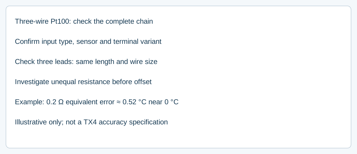
Trả lời trực tiếp: A three-wire Pt100 circuit reduces lead-wire effects by relying on a relationship between the leads, but unequal lead resistance can leave a measurement error. Confirm the actual controller input and terminal arrangement, keep the three leads matched as the manufacturer requires, and investigate resistance imbalance before applying a display offset. Three wires do not make every cable error disappear.
What is the three-wire assumption?
A Pt100 is a resistance temperature detector (RTD): its resistance changes with temperature. Connecting it to a controller requires lead wires, whose resistance also contributes to the measurement. A three-wire input uses its measurement arrangement to compensate for lead resistance under a matching assumption. If the relevant leads differ, compensation can leave a residual error; the exact effect depends on the controller’s measurement circuit and where the mismatch occurs. Emerson’s RTD sensor documentation discusses three-wire compensation and the distinct four-wire approach.
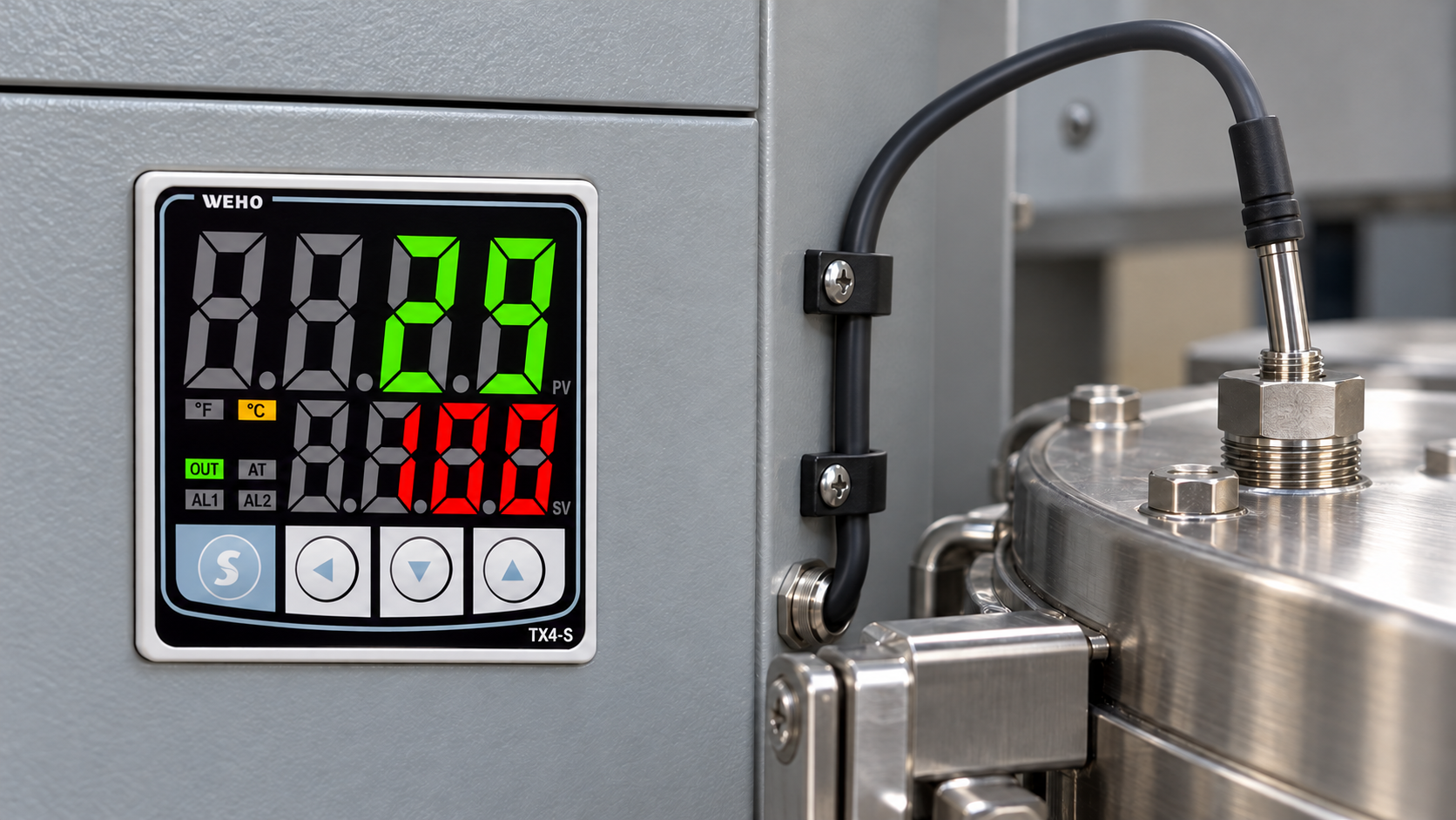
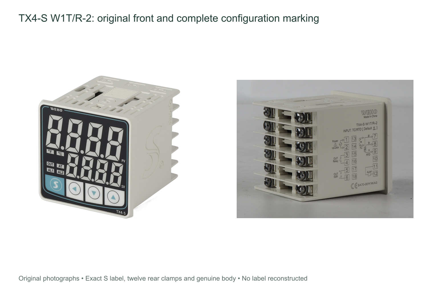
các WEHO TX4 manual lists Pt100 and Cu50 RTD inputs and calls for three RTD wires of equal thickness and length. The TX4-S product page also lists Pt100. Select the actual input type and consult the supplied manual for the exact model and hardware version. TX4 sizes use different terminal layouts; do not transfer terminal numbers from a different case size.
How much can a resistance error matter?
Near 0 °C, a common Pt100 with an alpha of 0.00385 has an approximate sensitivity of 0.385 Ω/°C. If an independently established equivalent uncorrected resistance error were 0.2 Ω at the input, its approximate temperature effect near 0 °C would be:
0.2 Ω ÷ 0.385 Ω/°C ≈ 0.52 °C.
This is a hypothetical conversion, not a measured TX4 error or an accuracy guarantee. It does not mean that every 0.2 Ω difference between any two wires produces 0.52 °C error: that depends on the input circuit and which lead differs. Sensitivity changes over the temperature range, and sensor tolerance, input accuracy, connection resistance and calibration all add to the uncertainty budget.
Which checks belong in the purchase and installation record?
| Mục | What to check | Why it matters |
|---|---|---|
| Controller and configuration | Exact TX4 size, suffix, approved input setting and current manual | Input and terminal mapping must match the installed unit. |
| cảm biến | Pt100 type, temperature range, tolerance and compatible three-wire arrangement | Different RTD types and tolerances change interpretation. |
| Lead extension | Three matching conductors, length, material, gauge and connection quality | Unequal resistance can defeat part of the compensation. |
| Test record | Reference instrument, conditions and observed readings over required range | Shows the complete chain, not only a nominal specification. |
Omron’s sensor extension FAQ addresses the importance of matching the RTD extension wires. Its instructions apply to the devices and conditions described there; follow the actual TX4 and sensor documentation for the selected assembly.
Investigate a reading offset in a controlled sequence
- Record the precise sensor and controller identifiers, input setting, terminal layout, cable construction and extension length.
- Use the installation procedure to isolate power and have a qualified person inspect terminals and joints. Follow the approved measurement procedure before disconnecting an RTD.
- Measure and compare the leads using a method and instrument appropriate for low resistance; include connector and test-lead effects. Look for mismatched extensions, joints, damage or corrosion.
- Compare the installed measurement chain against a suitable reference at the relevant process conditions. If possible, check more than one temperature to distinguish a constant offset from a range-dependent error.
- Correct a verified wiring or configuration problem, then re-test. Apply any permitted offset only after the residual error is understood; an offset can conceal a changed connection and does not improve sensor tolerance.
Do not assume that a four-wire sensor can be connected as a four-wire input to TX4, or that a controller’s temperature alarm provides independent safety protection. Use only the wiring configuration and safety architecture documented for the actual installation.
Identify the right TX4 before ordering
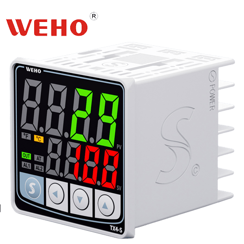
TX4-S is one physical version in the TX4 family. Request the exact model, supply and output variant, current wiring instructions and Pt100 configuration from WEHO. The manufacturer product illustration below identifies the family size; it is not a view of the rear terminals or proof of a field installation.
Frequently asked questions
Does equal wire length guarantee equal resistance?
No. Material, gauge, joints and condition also affect resistance. Equal length and thickness are part of the manual’s requirement, and the installed circuit still needs inspection and verification.
Should I correct every mismatch with a display offset?
No. Find and correct the cause first; assess the remaining measurement uncertainty and verify at the relevant temperatures. An offset does not establish the integrity of a changing connection.
Send WEHO the TX4 size and suffix, Pt100 type, cable length and required measurement range. Request the applicable model documentation and agree on a complete-chain acceptance test. Liên hệ với WEHO.