A bidirectional DC-DC converter must support controlled power transfer in both required directions, with documented voltage, current and control limits for each mode. A one-way supply surviving a brief reverse-current event is a different capability. Before choosing a converter, define the two ports, their energy sources and receivers, and who controls each transfer.
This guide is for an OEM specifying a two-port DC energy interface. It is not a claim that a standard WEHO DC-DC product supports bidirectional operation, battery charging or regenerative power. Those functions need evidence for the exact offered configuration.
On this page
Define power flow before choosing buck or boost
“Bidirectional” describes the permitted direction of energy transfer. “Buck” and “boost” describe a voltage-conversion relationship. They are not interchangeable labels. If port A operates at a higher positive voltage than port B, A-to-B transfer can be step-down while B-to-A transfer is step-up. The converter must still be designed and controlled for both modes.
Texas Instruments’ TIDA-00476 reference design illustrates this distinction with a power stage used in synchronous buck and boost operation for transfer between a DC source and storage. That design is a teaching reference, not evidence that another converter supports its functions, control firmware or operating envelope.
Also state whether voltage polarity changes. Reversing current between two positive-voltage ports does not automatically create a four-quadrant bipolar supply. Use a drawing with explicit polarity references and signed currents; avoid a vague arrow marked “reversible.”
Specify every required mode as a separate row
| Mode | Conditions to define | Evidence required |
|---|---|---|
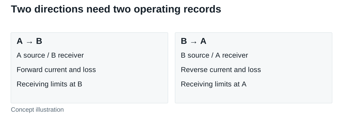
| A supplies B | Both voltage windows; delivered power; receiving-port limits | Ratings, losses, regulation and protection for this direction |
| B supplies A | Reverse transfer demand and receiving capacity at A | Independent reverse-direction ratings and control behavior |
| Zero-transfer standby | Which ports remain energized; allowed standby consumption | Permitted terminal conditions and unwanted-current limits |
| Direction change | Initial state, command, allowed interruption and transition demand | Controlled transition record against agreed limits |
| Receiver unavailable | Full storage, disconnected receiver or a bus unable to accept power | Defined curtailment, stop or alternative energy-management response |
| Fault and restart | Port loss, protection event and restart conditions | Model-specific response, recovery and supervisory requirements |
Specify the applicable power for each direction rather than assuming symmetry. A “500 W” headline may omit whether that value applies in both directions, throughout both voltage windows, continuously, or only under a particular cooling arrangement. Record those conditions before comparing prices.
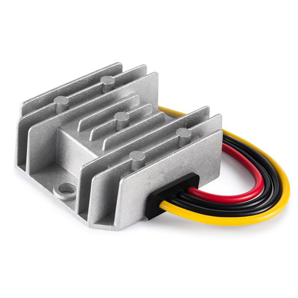
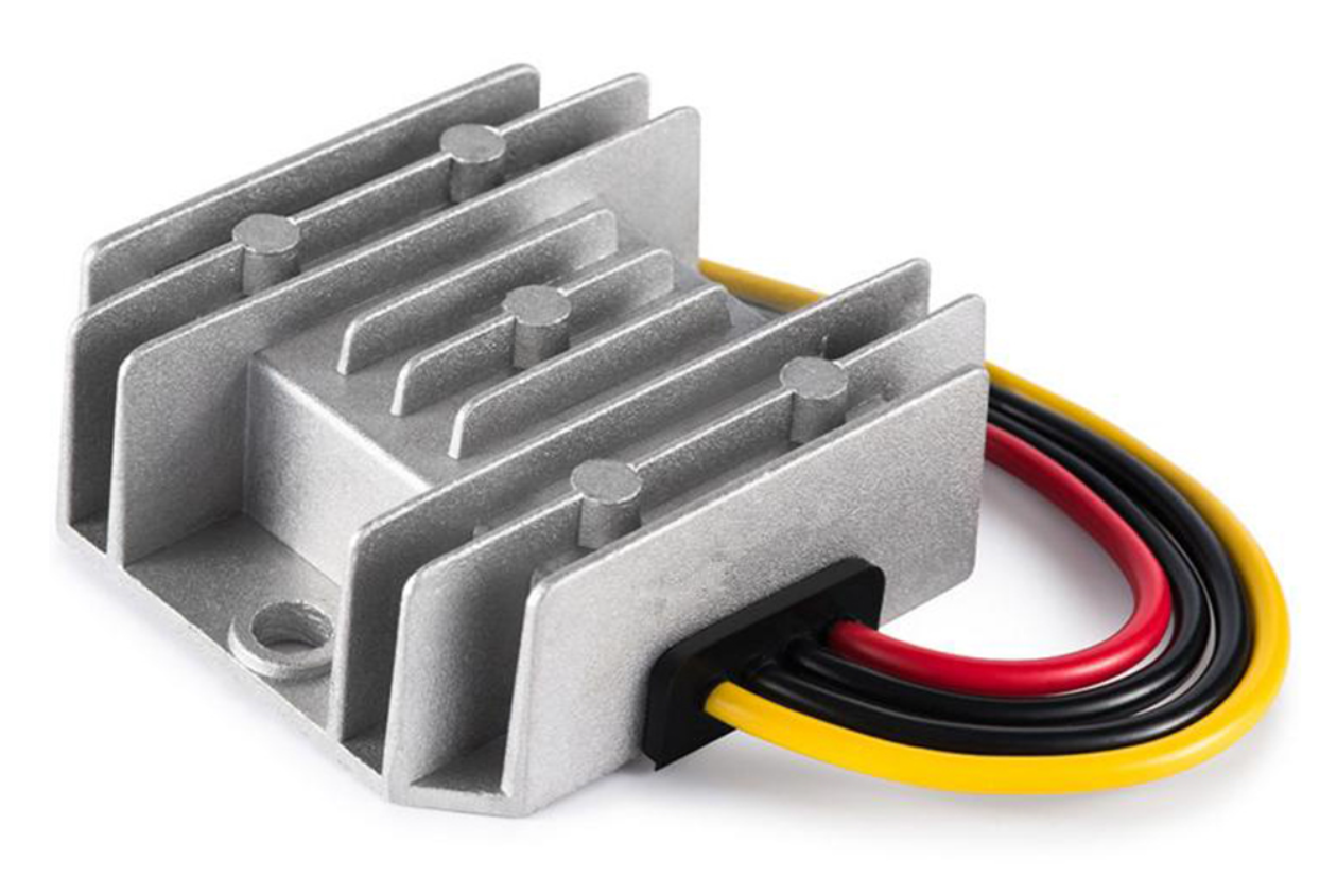
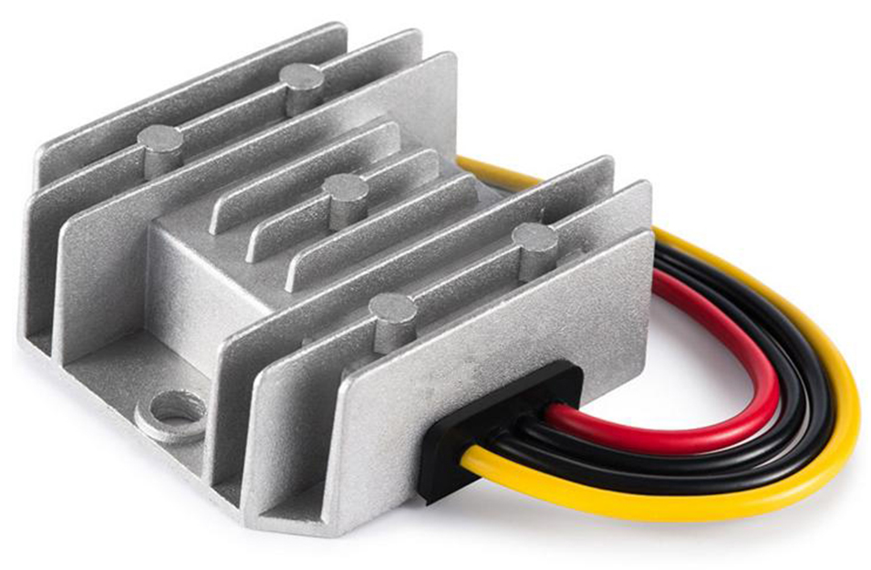
A forward-rating document can make missing bidirectional fields explicit. For comparison, the public WH-C241210 specification lists a nominal 24 V input and a 12 V, 10 A output for WEHO WH-C241210. That output row does not qualify a controlled 12 V-to-24 V reverse-transfer mode. In the mode matrix, retain the reverse-direction rating, receiving limits and control behavior as unestablished until exact-model evidence supplies them; do not fill those cells by reversing the forward numbers.
Calculate both sides of each transfer
Hypothetical requirement example: let port A be 48 V and port B be 24 V at the calculation points. These are fixed example values, not battery operating ranges. Define a positive current as entering the converter at that port.
For A-to-B transfer, assume B must receive 240 W and an illustrative conversion efficiency is 94%. Required input power at A is 240 ÷ 0.94 ≈ 255.32 W. Current at A is 255.32 ÷ 48 ≈ 5.32 A; current delivered into B is 240 ÷ 24 = 10 A. The converter therefore has approximately +5.32 A at A and −10 A at B under the chosen convention.
For B-to-A transfer, assume A must receive 192 W and an illustrative reverse-direction efficiency is 92%. B must supply 192 ÷ 0.92 ≈ 208.70 W, hoặc 208.70 ÷ 24 ≈ 8.70 A. A receives 192 ÷ 48 = 4 A. The corresponding port currents are −4 A at A and approximately +8.70 A at B.
The losses are approximately 15.32 W and 16.70 W respectively. These calculations do not establish cooling, rating or suitability; they show why current and loss must be checked in both modes. A converter that meets one direction’s current requirement may still fail the other. Repeat the budget at the actual voltage extremes using supported efficiency information.
Assign control ownership and receiving limits
Identify which controller commands direction, which quantity is regulated and which device sets the allowable current. A regulated bus, a battery-management system and a converter cannot be assumed to coordinate merely because their nominal voltages match. Preserve communication interfaces, default states and the response to lost commands in the requirement.
If a port connects to a battery, obtain the chemistry-specific charging requirements, management limits and protection architecture. Bidirectional energy transfer alone does not establish an approved charge profile, balancing, termination or permission to charge the pack. Similarly, a DC bus may be able to supply power while being unable to receive it.
Include the state in which one port is powered while the other is absent or at a different potential. The requirement should identify allowed terminal conditions and the supported isolation or disconnect behavior. Do not equate a software zero-power command with electrical isolation.
Qualify transitions as well as steady transfer
Agree the observable limits before requesting captures. At minimum, identify the required voltage and current bounds, transfer command, interruption tolerance, ramp behavior and protection response. Keep source impedance, cables, local storage, port capacitance, firmware and cooling with the configuration record.
The deliverable is a mode-by-mode result with evidence or a named open item. If the receiving system cannot accept energy in a required state, resolve that system limitation before declaring the converter suitable. Testing only a stable forward-power point leaves the central bidirectional question unanswered.
Send a two-port specification
Provide WEHO with both voltage windows, each direction’s required delivered power, load/source types, control ownership, transition requirements, insulation needs and thermal conditions. Ask which exact configuration, if any, can be evaluated against that specification. A conventional single-direction converter should not be presented as a substitute without the required evidence. State whether the requirement is controlled power transfer in both directions or prevention of unwanted reverse backfeed in an otherwise one-way system. Those are different requests; the inquiry should identify the function before any product or protection arrangement is proposed.