



Key Engineering Takeaways
- A driver's 300–500 VAC input range does not qualify the external components that switch or connect its AC feed.
- Check contact working voltage, switching duty and applicable installation conditions separately from a relay's coil voltage.
- The HVG-250-24 is the 24 V-output product reference; its output voltage does not define the voltage across upstream contacts.
- Release a component-by-component evidence record before approving the complete high-line switching path.
The Driver Input Range Is Only One Boundary
An OEM may identify a lighting driver whose published input range includes the plant supply, then overlook a control relay, connector or service device carried over from a lower-voltage design. The driver can match the intended input while another component in the same path remains unqualified.
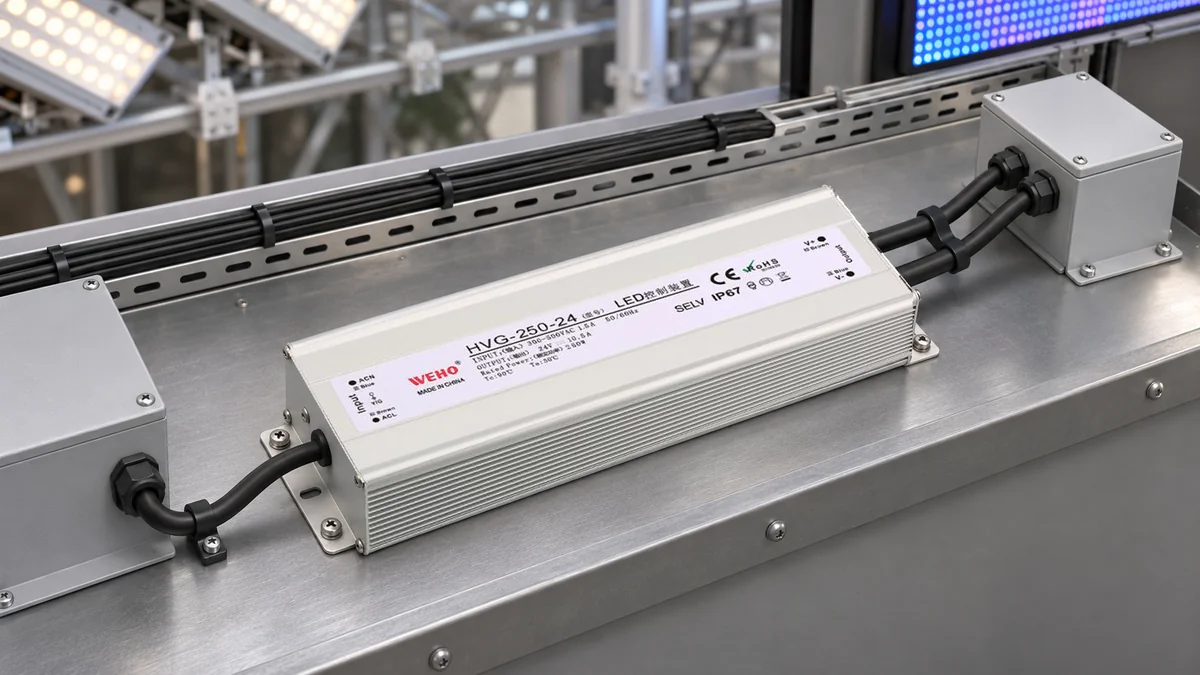
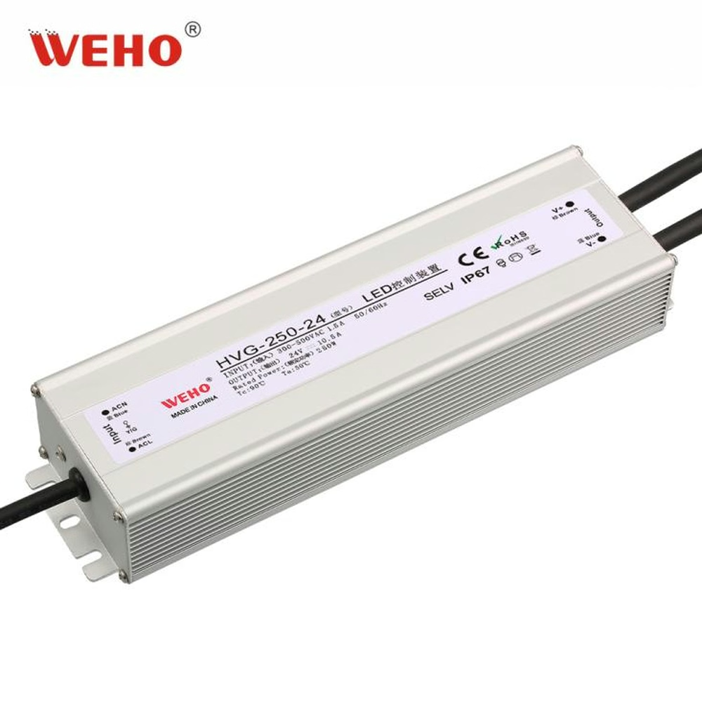
các WEHO HVG-250-24 product page publishes a 300–500 VAC input range. This article addresses the external AC switching and connection path. It does not provide a plant wiring diagram, establish a three-phase connection arrangement or approve a particular relay for the installation.
Draw the Path Whose Ratings Must Be Checked
Identify the actual conductors and components that feed the driver. Record the source characteristics established by the equipment's electrical design, then mark the devices through which those conductors pass. These can include switching contacts, connectors, terminals and the relevant protective or disconnecting equipment.
Do not assume that every component sees the same electrical condition. The voltage across an open switching contact, a control coil's operating voltage and the voltage from a conductor to an accessible enclosure answer different questions. The circuit and applicable product instructions determine the relevant boundaries.
The HVG input range does not establish how a multi-phase plant supply should be connected. A qualified design must identify the actual conductor-to-conductor feed and the necessary switching, protection and earthing arrangement. The separate actual AC-feed review addresses that earlier supply-definition task.
Once the feed is defined, preserve it in the component review. A description such as “380 V factory” is too incomplete to replace the actual source record, operating bounds and equipment connection drawing.
| Path item | Rating question | Required source | Commonly confused item |
|---|---|---|---|
| Switching contacts | Permitted switching voltage and load duty | Exact device’s contact ratings and application data | Coil operating voltage |
| External connector | Applicable working voltage and installed conditions | Exact contact, insert and housing documentation | Current rating alone |
| Terminal arrangement | Applicable voltage, conductor and installation conditions | Exact terminal and equipment instructions | A visually similar terminal |
| Protection or disconnection | Duty required by the actual equipment design | Selected device’s applicable ratings and design review | The driver’s own input range |
| LED driver input | Exact model’s applicable source limits | Revision-matched manufacturer information | The 24 V output designation |
Keep Coil Voltage and Contact Voltage Separate
A relay operated by a 24 V control signal can have contacts assigned to an entirely different circuit. The coil rating therefore cannot establish whether those contacts can switch a 380 V AC driver feed. Conversely, a high contact-voltage marking does not establish the correct coil supply.
OMRON's relay precautions require selection within the applicable contact ratings and evaluation under the actual switching conditions. They also distinguish coil application from the contact's load duty. Use the selected relay's own specifications to resolve both; a generic “industrial relay” description is insufficient.
The driver's DC output is another independent boundary. Choosing an HVG-250-24 because the receiver needs 24 V does not reduce the voltage across an upstream AC switching component. Trace the actual circuit rather than transferring a convenient low-voltage number from one side of the driver to the other.
Also keep operational ratings separate from dielectric-test statements. A withstand-test entry describes a defined test boundary and condition; it is not automatically a permitted repetitive switching voltage. Request the rating that answers the actual circuit duty.
Work Through a High-Line Component Review
Consider a hypothetical OEM review in which the approved design calls for a 380 VAC feed within its defined operating conditions. The proposed source candidate is an HVG-250-24, whose current product listing states a 300–500 VAC input range. A copied bill of materials includes an external relay with a hypothetical maximum AC switching-voltage rating of 250 VAC.
Assume the reviewed circuit can place the 380 VAC feed across the relevant open contact. The proposed contact rating then fails that stated voltage screen: 380 V is above 250 V. A low measured running current would not erase the voltage mismatch.
This example uses an invented relay rating to explain the decision. It is not an evaluation of a particular commercial relay or the complete installation. The design team must also confirm the source bounds and the device's applicable conditions before a replacement can be selected.
Adding another contact in series is not an automatic way to multiply the permitted voltage. Voltage sharing, contact operation and the manufacturer's allowed arrangement would need their own evidence. Do not turn a failed component screen into an undocumented series-contact solution.
| Hypothetical proposal | Known information | Review result | Required next step |
|---|---|---|---|
| HVG-250-24 input candidate | Published 300–500 VAC input range | Range is relevant to the defined 380 VAC feed | Confirm applicable revision and remaining conditions |
| Copied relay contact | Assumed 250 VAC maximum switching voltage | Does not cover the stated 380 VAC contact duty | Select a documented suitable device |
| Relay coil | Separate control supply required | Not resolved by the contact rating | Match the actual control circuit |
| Complete path | Connector and other device evidence incomplete | Driver selection alone cannot release the path | Close every applicable component item |
The final row is often the most useful. It prevents a correct power-supply input specification from becoming a blanket approval for unrelated components. An unresolved component is a specific action item rather than evidence that the driver itself is unsuitable.

Swipe horizontally on a small screen, or open the full-size diagram.
Add Switching Duty Without Guessing From Running Watts
A contact that satisfies the relevant voltage screen still needs the appropriate current and switching-duty evidence. A switch-mode input can present a startup event unlike its steady running current. The selected device's make, carry and break capabilities need to match the actual task.
The HVG-250 product table publishes a cold-start inrush value of 30 A at 380 VAC. That single peak does not supply a pulse duration, a complete current waveform, a guaranteed number of parallel drivers or a relay-life result. Use it as a reason to request the missing duty information, not as a complete selection equation.
The external component supplier may provide limits for a specified lighting or capacitive-input load, or require application testing. Preserve the exact conditions and source rather than translating a resistive-load rating into an unsupported driver count.
For this article's decision, keep the voltage check and switching-duty check on separate rows. A passed current calculation cannot compensate for a failed working-voltage requirement, and a suitable working-voltage rating does not settle the startup duty.
Release the Evidence in a Defined Order
- Confirm the feed. Record the actual supply definition and operating bounds from the equipment's approved design. Resolve ambiguous conductor names before evaluating components.
- Identify every path component. Record full part numbers and options, including sockets or inserts where they affect the rating. A family name is not a released bill of materials.
- Check the relevant voltage boundaries. Compare the documented component ratings with the actual duty. Keep coil, contact, insulation-test and working-voltage information distinct.
- Check switching and environmental conditions. Obtain applicable load-duty and installation information, including startup behavior where relevant. Do not infer these from the driver's output power.
- Close specific gaps. Request missing manufacturer information or revise the proposed component. Preserve the question and its resolution with the equipment revision.
- Verify the complete assembly. Qualified personnel should perform the required inspection and controlled validation under the equipment's procedures. This document review is not a substitute for that verification or an instruction to test exposed high-line circuits.
Download the high-line AC-path review worksheet. Its component rows help purchasing, controls engineering and the equipment reviewer refer to the same proposed parts and unresolved requirements.
Ask WEHO for Revision-Matched HVG-250 Input Information
For an HVG-250-24 application inquiry, provide the defined AC feed, intended switching arrangement, driver quantity, operating sequence and proposed external components. Ask for the applicable input documentation and available startup-duty information. Keep the external components' ratings with their own manufacturers' evidence rather than treating the driver page as their approval.
Engineering FAQ
Does a 300–500 VAC driver rating qualify every upstream relay?
No. The driver input range applies to the driver. Each external switching or connecting component needs applicable ratings for the actual voltage, current, duty and installation conditions it experiences.
Can a 24 V relay coil switch a high-line AC feed?
The coil voltage does not answer that question. Check the selected relay's contact ratings and actual circuit duty separately, while also matching its coil to the control supply.
Is a relay acceptable if its current rating is higher than the driver's running current?
Not on that evidence alone. The voltage rating, applicable switching duty, startup event and installation conditions also matter. A passed running-current comparison cannot correct an unsuitable voltage rating.
Can two contacts in series automatically double the switching-voltage rating?
No. Any series-contact arrangement needs explicit manufacturer and equipment-design support for the actual duty. Do not assume equal voltage sharing or an increased rating from the contact count alone.



