



Key Engineering Takeaways
- Thermocouple wire condition and the temperature gradient along that wire jointly affect the generated voltage.
- Moving a used probe can change its error even when the measuring junction reaches the same temperature.
- A controller simulator check cannot establish the homogeneity of the installed thermocouple.
- Record immersion, routing and exposure history before transferring a correction between installations.

1. Investigate the changed installation before changing the offset
A thermocouple that changes its indication after repositioning needs an installation investigation before a new offset is approved. A repeatable electrical check of the receiver does not reproduce the thermal gradient experienced by the working wire. Separate the receiver, the junction's actual temperature and the wire's thermoelectric condition in the investigation record.
For an installation using a WEHO TX4-S temperature controller, identify the actual input selection, probe type and complete ordered controller code. The product identity establishes the receiver under discussion; it does not certify the connected probe's homogeneity or the transferability of a calibration correction.
2. Distinguish wire inhomogeneity from connection errors
Thermocouple inhomogeneity means that the Seebeck coefficient varies with position along the thermoelement wires. The voltage effect depends on where the temperature gradient intersects those variations. BIPM describes evaluating this mechanism by moving wire through a controlled gradient while observing voltage, rather than treating the sensing junction as the sole source of thermoelectric behavior. BIPM thermocouple calibration guide, section 4.1.2
Correct alloy, polarity and cold-junction arrangements still matter. A reversed extension conductor or an unsuitable connector can produce a different fault that also changes with temperature. Use the WEHO K-type thermocouple and TX4 connection guide to organize that separate connection check; passing the check does not eliminate inhomogeneity.
Used wire may have a different thermoelectric state from unused wire of the same nominal type. Fluke explains why relocating an aged thermocouple relative to a thermal gradient can change its error. A calibration result therefore needs installation conditions, not simply a temperature and a correction number. Fluke Calibration thermocouple fundamentals
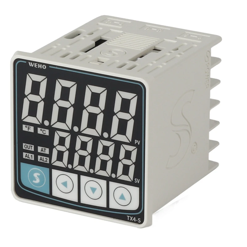
Treat thermal history as an equipment record. Include the heated length, earlier insertion depth, maintenance bends, replaced extension sections and any suspected contamination. NPL identifies thermoelectric inhomogeneity and its evolution as practical contact-thermometry research problems; the issue is not resolved by selecting a more precise display format. NPL contact thermometry
3. Calculate a deliberately simplified gradient example
Consider a hypothetical wire segment whose effective pair Seebeck coefficient differs from the reference by a constant +0.20 µV/K. Assume that this segment experiences a 100 K temperature rise along its length in arrangement A, a 25 K rise in arrangement B and no temperature rise in arrangement C. The measuring and reference junction temperatures are otherwise unchanged.
For this restricted model, the additional voltage is ΔE = ΔS × ΔTsegment. The results are +20 µV, +5 µV and 0 µV. Assume a local readout conversion slope of 40 µV/°C only to express those voltage differences as illustrative temperature equivalents: ΔTindicated = ΔE / 40. These inputs are invented teaching assumptions, not measured wire properties or universal Type K coefficients.
| Hypothetical arrangement | Rise across changed segment | Additional voltage | Illustrative temperature equivalent |
|---|---|---|---|
| A: segment spans most gradient | 100 K | +20 µV | +0.500°C |
| B: segment partly in gradient | 25 K | +5 µV | +0.125°C |
| C: segment is isothermal | 0 K | 0 µV | 0°C from this mechanism |
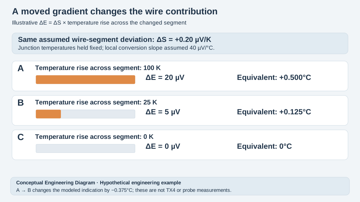
Swipe horizontally on a small screen, or open the full-size diagram.
Moving the segment from A to B changes the modeled indication by −0.375°C without changing either junction temperature. The example isolates a mechanism; an actual probe has spatially distributed, temperature-dependent properties. Other wire sections, heat conduction and reference-junction conditions can contribute additional errors, so the simple calculation is not a prediction for an installed TX4 system.
The 40 µV/°C assumption also limits the conversion. For an actual investigation, use the appropriate thermocouple reference function and local sensitivity at the operating point. Do not divide every measured microvolt difference by the same rounded number over an entire process range or convert a positional effect into a permanent controller correction.
4. Build comparisons that separate the possible causes
A useful comparison holds the receiving chain constant while documenting the thermal arrangement. A qualified temperature-calibration procedure may compare different immersion positions against a reference, with sufficient stabilization and immersion control. Simply pulling the probe out during production changes the junction temperature, heat losses and process conditions together; that observation cannot isolate wire inhomogeneity.
Receiver simulation has a narrower purpose. Use an appropriate source and the actual input configuration to investigate the controller's electrical receiving path, following the applicable TX4 documentation. Do not connect an arbitrary voltage to an unidentified terminal or assume that a successful simulation includes the probe and installation. WEHO TX4 instruction manual
| Comparison | Keep or record | Question answered | Limit of conclusion |
|---|---|---|---|
| Receiver with suitable simulator | Input type, source mode, terminals | Does this electrical path indicate consistently? | No wire-homogeneity evidence |
| Installed probe against reference | Position, process state, stabilization | What is the installed disagreement? | Several thermal errors remain combined |
| Controlled positional comparison | Junction temperatures and gradient arrangement | Does disagreement depend on wire position? | Not a formal scan unless method supports it |
| Documented replacement probe | Construction, routing and immersion | Does the changed assembly improve agreement? | Does not identify every old-probe mechanism |
Preserve unsuccessful comparisons too. A result with an unstable reference or changing process load should be marked inconclusive, with the reason retained. Removing inconvenient readings from the record makes a replacement decision appear more certain than the method supports and prevents the next maintenance team from reproducing the investigation.
5. Execute a controlled investigation and release decision
- Identify the complete chain. Record controller code, selected input, thermocouple type, extension construction and connector identities. Verify these against the actual labels and applicable documentation before interpreting any temperature disagreement.
- Freeze the installed geometry. Photograph the insertion mark and routing, and record the heated length and previous position. Verify that the proposed comparison can reproduce the same junction location without disturbing a hazardous or operating process.
- Check the receiving path separately. Record the appropriate simulator settings, indicated values and terminal conditions under an approved procedure. Verify that a receiving-path error is not being hidden inside the probe investigation.
- Compare controlled thermal arrangements. Record the reference temperature, stabilization criterion, immersion and wire position for each condition. Verify that junction-temperature changes and insufficient immersion cannot reasonably explain the observed difference before attributing it to inhomogeneity.
- Limit the correction or replacement decision. Record which probe and arrangement the evidence covers, the uncertainty and the required recheck after relocation. Verify that acceptance addresses the process tolerance rather than a visually stable display alone.
An offset may improve agreement in one fixed installation while worsening another arrangement. The release record should therefore identify the tested geometry and its limits. If the available evidence cannot separate immersion error from a positional wire effect, retain that uncertainty and obtain a suitable laboratory investigation instead of assigning a definitive failure mechanism.
6. Send WEHO the receiving-chain and installation record
Send WEHO the complete TX4-S controller identity, probe and extension specifications, insertion photographs and paired reference readings. Include any independent simulator result and the exact maintenance change that preceded the disagreement. These details make a controller-input inquiry distinguishable from a probe replacement or calibration-method question.
The next action is to preserve the current geometry record, resolve the receiving-chain evidence and define an acceptable installed comparison. Release a correction only for the documented conditions; require a fresh review when the heated wire length, routing or probe assembly changes.
7. Frequently asked questions
Can moving a thermocouple change its error without changing the junction temperature?
Yes, moving an inhomogeneous wire relative to the thermal gradient can change its generated voltage even when the junction temperatures are unchanged. An actual positional comparison must also control immersion and reference conditions before this mechanism can be distinguished from other thermal effects.
Does a successful controller simulator test prove that the thermocouple is accurate?
No, an electrical simulator test does not establish the homogeneity or installed thermal behavior of the thermocouple. Record exactly which receiver configuration and terminals were checked, then assess the probe and its installation with a suitable temperature-reference method.
Can a laboratory correction be transferred after changing insertion depth?
A correction should not be transferred to a changed insertion arrangement without evidence that its stated conditions remain applicable. Ask the calibration provider about the tested geometry, thermal history and uncertainty before adopting the correction in a different installation.
Should every positional disagreement be corrected with a TX4 offset?
No, a positional disagreement needs its cause and operating boundary investigated before an offset is approved. Incorrect connections, immersion changes, reference conditions and wire inhomogeneity can require different remedies, and one fixed offset may not address a changing gradient.


