



Key Engineering Takeaways
- The C3Z-D100N product page describes five presses to switch NO/NC action.
- NPN output type and NO/NC action are separate configuration questions.
- Check target condition, sensor output, receiver bit and machine interpretation together.
- Do not infer retained mode, fault detection or safety performance from an inverted signal.
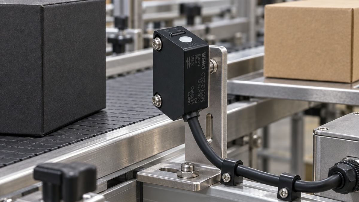
Why can a mode change reverse the machine response?
A configurable output can change which target condition produces an active signal. If a technician changes NO/NC action while the PLC program remains unchanged, a previously meaningful input bit may acquire the opposite meaning. A working detector can then be interpreted incorrectly by the machine.
Der C3Z-D100N photoelectric sensor information identifies an NPN diffuse-reflective option and describes switching NO/NC action with five presses. For an OEM commissioning engineer, the task is to verify the resulting relationship between the actual target and the receiving input, rather than accepting a button action as proof of the final configuration.
Keep the equipment in its defined commissioning condition while changing detection logic. The sensor action, program interpretation and process permission need a coordinated review before normal machine operation resumes.
How do output type and action mode differ?
NPN describes an electrical output arrangement. NO/NC describes the intended switching action in relation to the defined detection condition. Changing one does not establish the other. The general distinction between NPN and PNP sensor outputs is useful background, while the WEHO connection drawing remains the relevant product reference.
Der C3Z-D100 dimension and wiring drawing shows the NPN receiver circuit with brown connected to +V, blue to 0 V and black as the output. The illustrated load is between +V and the black output. Match the actual receiver circuit, supply, load current and input thresholds before connecting the sensor.
The product table specifies a 10–30 VDC supply and a maximum load current of 100 mA. Those values do not by themselves establish compatibility with every PLC input. A receiving module also has its own input circuit and ON/OFF conditions, which must be checked in that module's documentation.
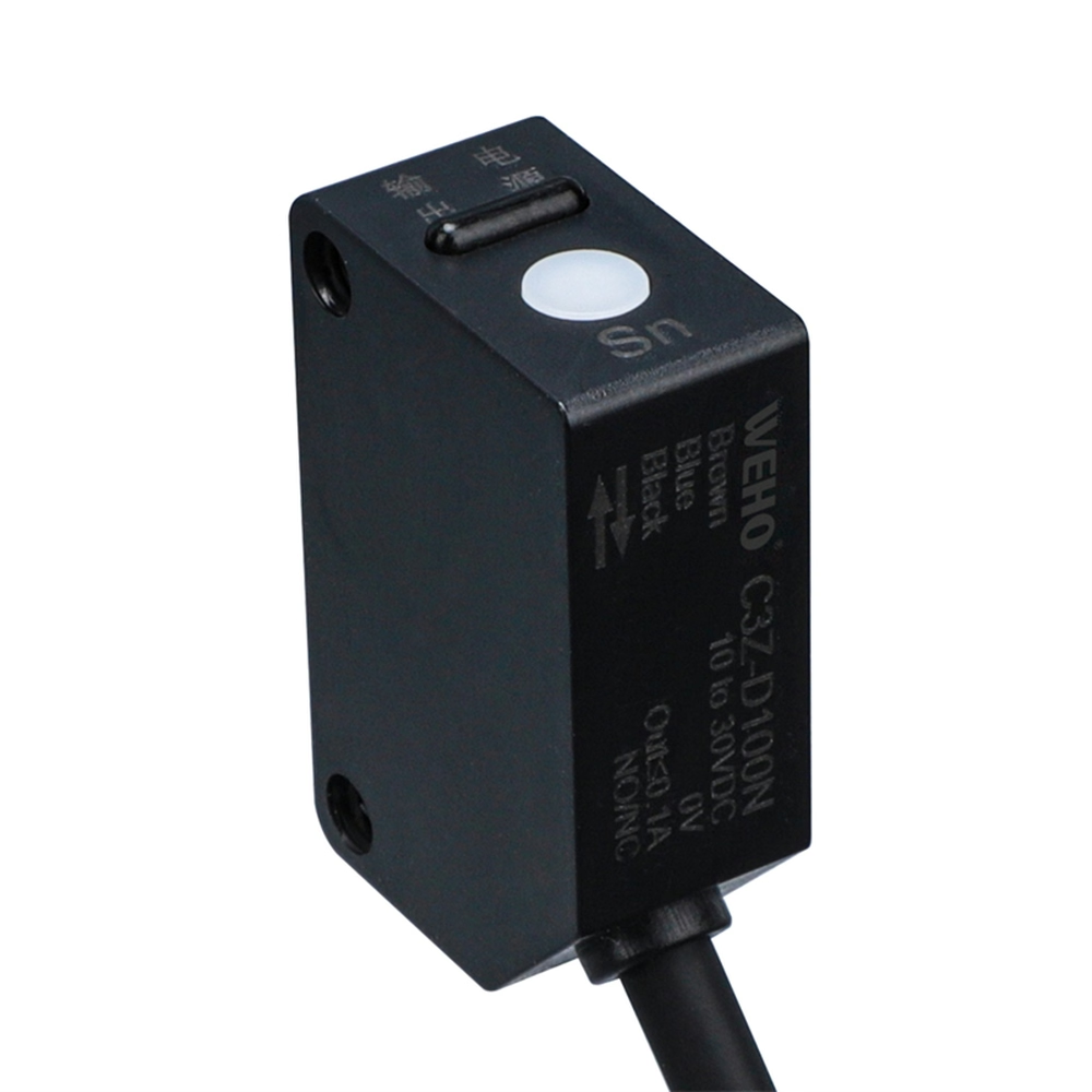
What should the machine regard as the active condition?
Define the required machine meaning before selecting the action mode. Examples include a workpiece present at a station, a fixture position occupied or a part clear of an optical path. These are application definitions; they cannot be supplied by the words NPN or NO alone.
For a diffuse-reflective sensor, the target and background must also be physically qualified. The C3Z-D100 table lists an adjustable 100 cm detection distance with a 10 × 10 cm white, non-glossy paper standard target. That published condition is not a guarantee for every dark, transparent, curved or reflective production object.
Begin with a target condition that the application has already defined and can reproduce. Otherwise, a weak or inconsistent detection result can be confused with a logic inversion. Correctly interpreting an unreliable optical event does not make the event reliable.
Separate the sensor's action indicator from the PLC bit. The page identifies a red action indicator and a green power indicator, but the final machine meaning still depends on the receiver and program. Record what each indication actually does during the test.
How can a state table expose a logic mismatch?
Use a Hypothetical Presence-Input Example. An OEM requires the PLC application signal PART_PRESENT to be true only when a qualified workpiece is at the sensing position. The rows below describe the desired machine result, without claiming an observed C3Z-D100N response or a specific PLC electrical convention.
| Qualified target | Desired application signal | Observe at sensor | Observe at PLC |
|---|---|---|---|
| Absent | PART_PRESENT = false | Action indicator and output state | Raw input and interpreted signal |
| Present | PART_PRESENT = true | Action indicator and output state | Raw input and interpreted signal |
| Returned to absent | PART_PRESENT = false | Repeatable return response | Correct signal clears |
| Present after approved mode change | Still requires explicit verification | Actual new output action | Agreement with intended program meaning |
Suppose the raw PLC input changes after the sensor mode is altered. That change can be electrically reasonable while the application signal becomes incorrect. Resolve the intended sensor mode and program interpretation together; do not add a software inversion merely to conceal an unexplained field configuration.
The table also distinguishes a command from its effect. Recording “five presses completed” shows an attempted configuration action. Recording target condition, output and interpreted signal shows whether the intended change was achieved.

Swipe horizontally on a small screen, or open the full-size diagram.
What should an engineer verify after the five-press action?
- Identify the actual C3Z-D100N marking and the receiving input module. Record the supply and applicable connection drawing before changing the action mode.
- Establish the target-present and target-absent conditions using representative, qualified objects and the intended background. Hold unrelated optical adjustments constant.
- Record the current action indicator, output state, raw input bit and application interpretation in both conditions. Preserve this baseline.
- Perform the documented mode-change action under the equipment procedure. The published page states five presses; it does not supply a complete timing or indicator sequence for every revision.
- Repeat the same target sequence. Compare the resulting output action and application signal against the approved state table.
- Check the required behavior after a permitted power cycle or replacement. Record what the actual unit does; do not assume that the mode is retained because the first test succeeded.
Use suitable equipment and qualified personnel for electrical checks. Isolate equipment before changing wiring. A logic check should not require operating uncontrolled motion or exposing personnel to the machine response being investigated.
What does an NC setting fail to establish?
An NC setting does not by itself provide wire-break diagnosis. Loss of sensor power, an open conductor, a shorted output or an optical fault can produce different electrical conditions. Whether the receiver can distinguish those conditions depends on the complete circuit and diagnostic design.
Likewise, an inverse action mode does not make the sensor a safety-rated protective device. Keep ordinary detection logic separate from any protective function required by the machine. The commissioning table should describe the actual intended process use without adding an unsupported safety claim.
Der C3Z-D100N output and target reference is the appropriate product entry for this review. Match the exact NPN model; a photograph showing C3Z-T15P-D or a PNP suffix represents a different identification and must not be used as proof of the installed D100N configuration.
What should be included in the technical handover?
Keep the selected action mode, target description, receiver model, wiring reference and application signal definition together. Include the observations before and after the mode change so a service engineer can distinguish a configuration change from a detection problem.
Use the NO/NC state-verification worksheet for that record. Send WEHO the C3Z-D100N configuration details, including any disagreement between the action indicator, output and PLC signal. Ask for revision-specific mode-setting information when the observed sequence cannot be reconciled with the applicable product documentation.
Engineering FAQ
Does changing NO/NC turn an NPN sensor into PNP?
NO/NC action and NPN/PNP output type are separate characteristics. A logic-mode change does not establish a different output circuit. Match the actual model and receiving input before wiring.
Are five button presses sufficient acceptance evidence?
Five presses document an attempted setting action. Acceptance requires observing the intended output and machine interpretation with qualified target-present and target-absent conditions after the change.
Does the red action light prove that the PLC input is correct?
The red light is one sensor indication. Verify the actual output, receiving input and program interpretation separately. A correct sensor indication can coexist with a mismatched receiver or an inverted application signal.
Can an NC setting be treated as broken-wire protection?
An NC setting alone does not establish broken-wire diagnosis or safety performance. Evaluate power loss and wiring faults using the actual receiver circuit and the machine's required diagnostic design.




