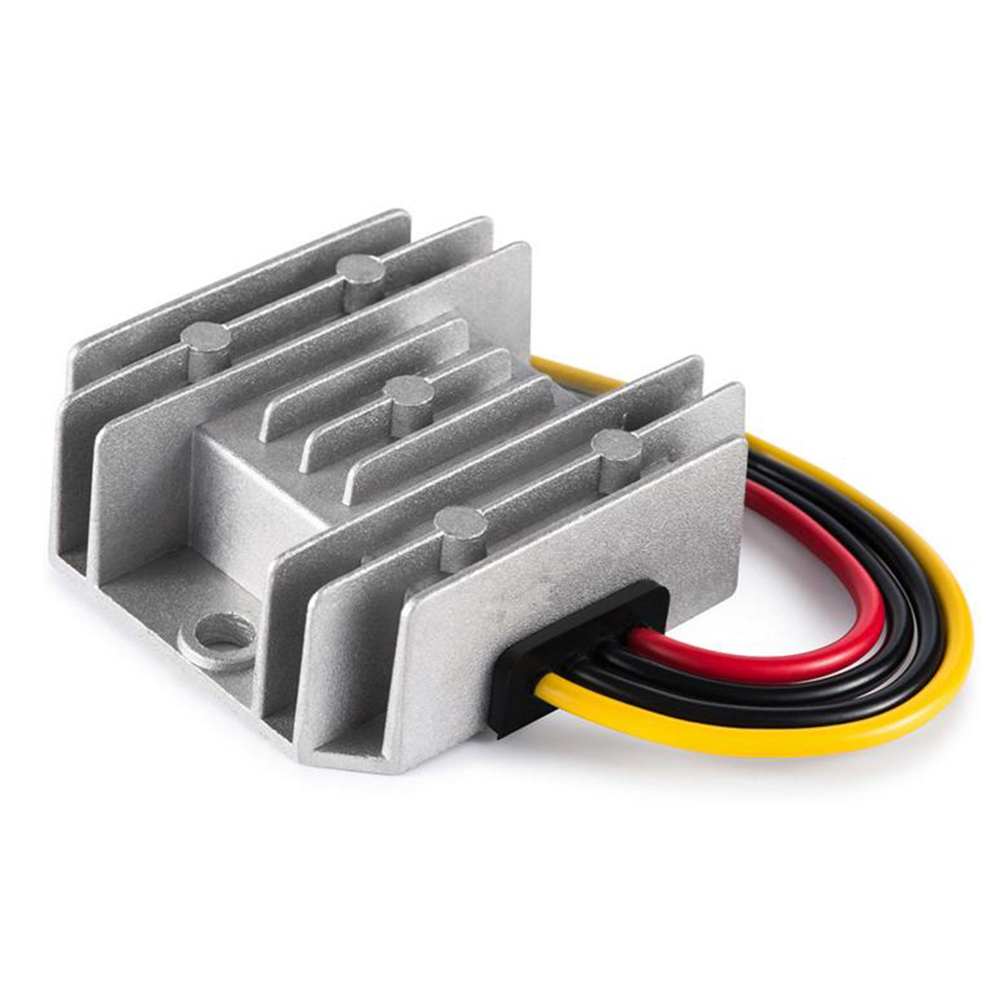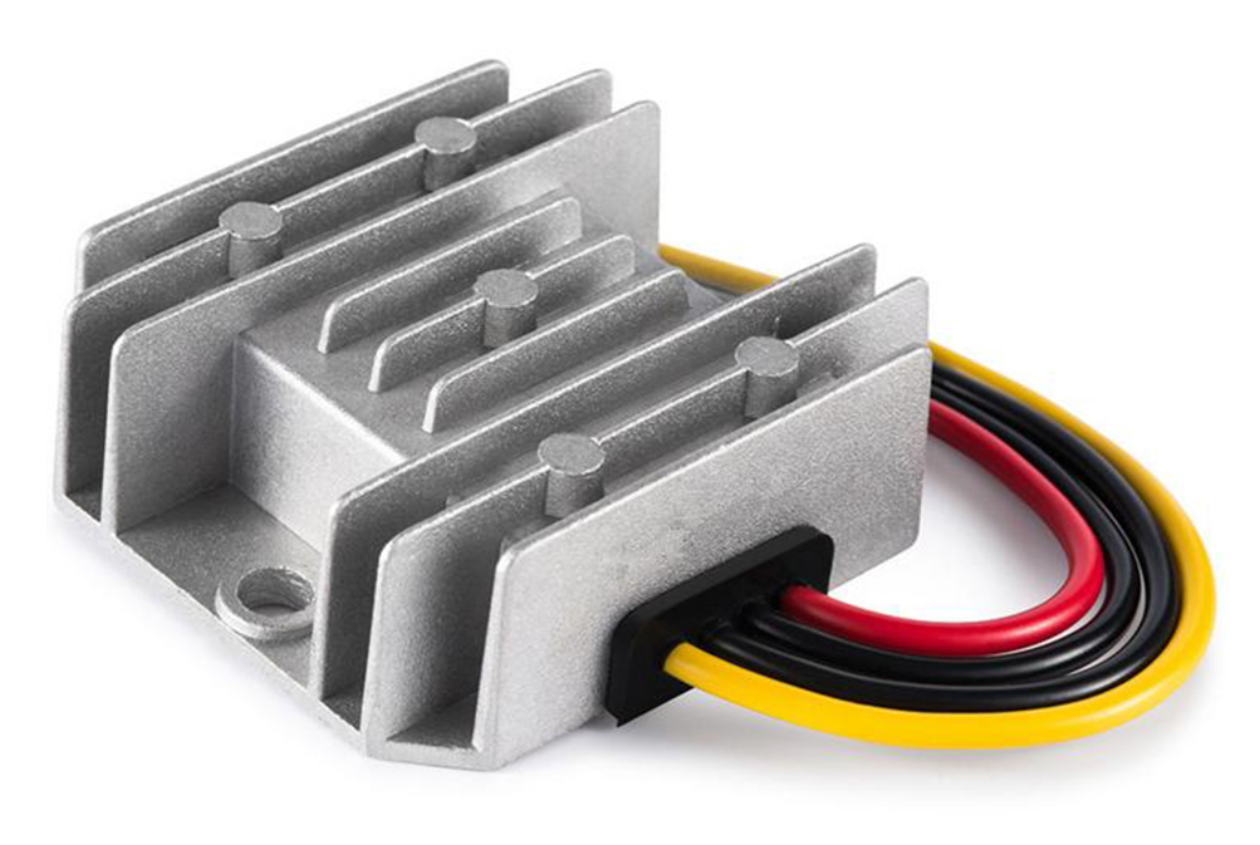
A DC-DC converter output capacitor must satisfy the converter’s documented capacitance and ESR requirements at the actual operating conditions. Selecting a larger nominal value, or the lowest available ESR, is not enough. Check the effective capacitance, permitted capacitor technology, total connected population and layout before qualifying the assembled rail.
This decision concerns the capacitor network connected to a finished converter or module. It does not authorize changing a sealed unit’s internal components. It also differs from checking whether a supply can charge a large downstream load at startup: successful charging alone does not establish acceptable steady operation or load-step response.
On this page
Treat capacitance, ESR and control behavior as separate constraints
The output capacitor stores charge, contributes to output ripple and participates in the converter’s dynamic behavior. A useful shortlist therefore records more than microfarads and voltage rating. Obtain the module manufacturer’s recommended parts, allowed capacitance range, ESR conditions and connection instructions for the exact output setting.
Murata’s output-ripple explanation separates the capacitance-related and ESR-related contributions to ripple. Reducing one contribution does not, by itself, demonstrate that the complete converter remains stable. Texas Instruments’ D-CAP output-capacitance example illustrates a control-specific stability constraint. Its component values and feedback modifications are not instructions for another converter.
Ask whether a limit applies to effective external capacitance, nominal installed capacitance, a named capacitor family, or the entire output network. Do not silently include or exclude capacitance already inside a module. A maximum capacitive-load entry may describe startup capability; it is not automatically a complete stability specification.
Compare the effective value, not only the part marking
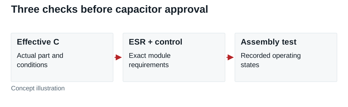
For some ceramic dielectrics, applied DC voltage changes capacitance. Murata’s DC-bias FAQ explains why the value under voltage can differ from the nominal value. Use the capacitor supplier’s data for the actual part, package, voltage and temperature. A voltage rating states a limit; it is not a promise of nominal capacitance at every voltage below that rating. For mixed ceramic, electrolytic or polymer networks, check each technology’s supplier capacitance and ESR data over the applicable temperature and frequency range rather than assigning one universal correction to the whole network.
Hypothetical screening example: assume a fictional module specification requires at least 100 μF effective external capacitance at the operating point. Suppose a candidate’s nominal value is 220 μF, its relevant tolerance lower bound is 80% of nominal, and an illustrative bias factor is 60%. If the supplied component data permit those factors to be combined in this way, the lower-bound estimate is 220 × 0.80 × 0.60 = 105.6 μF.
With a 50% bias factor instead, the same arithmetic gives 88 μF, below the assumed requirement. These factors and the 100 μF limit are invented for the calculation; they do not describe a WEHO module or a real capacitor. Actual supplier data may require a different method for combining tolerances and operating effects. For high-dielectric ceramic parts with documented aging behavior, include the supplier’s applicable time-dependent bounds in the effective-capacitance review.
This screen addresses only the minimum capacitance. It leaves maximum capacitance, ESR, ripple-current capability, voltage stress, temperature and lifetime requirements open. Doubling the capacitor population may solve one lower-bound problem while creating a different upper-bound or startup problem.
Use one record for the complete connected population
| Record | Include | Question to close |
|---|---|---|
| Converter identity | Exact model, revision, output setting and applicable document | Which capacitor requirements actually apply? |
| Capacitor population | Part numbers, quantities, local and downstream positions | Which parts contribute under each operating state? |
| Effective capacitance | Supplier curves, tolerance and operating-condition bounds | Are the required lower and upper bounds met? |
| ESR and ripple current | Relevant frequency, temperature and component ratings | Are control and component-stress requirements satisfied? |
| Physical connection | Placement, conductors, connectors and permitted layout | Does the real assembly match the documented arrangement? |
| Qualification evidence | Startup, load transitions, ripple and thermal observations | Does this configuration meet the project limits? |
Capacitance on a remote board is connected through real interconnect impedance. Do not assume that a large remote bank is equivalent to the specified local capacitor. Preserve the physical arrangement with the test record, particularly when a harness, connector or downstream board can change between equipment variants.
A concrete document example is WEHO WH-C241210. Its public specification identifies a 12 V, 10 A output and includes an external 22 μF capacitor with ESR below 0.1 Ω at 100 kHz in the ripple entry. Preserve that entry’s stated conditions with the document reference. It does not, by itself, define the complete allowed external-capacitance range, stability window or permission to substitute a different capacitor network. Obtain those model-specific conditions before releasing the connected assembly.
Validate the assembly and the replacement rule
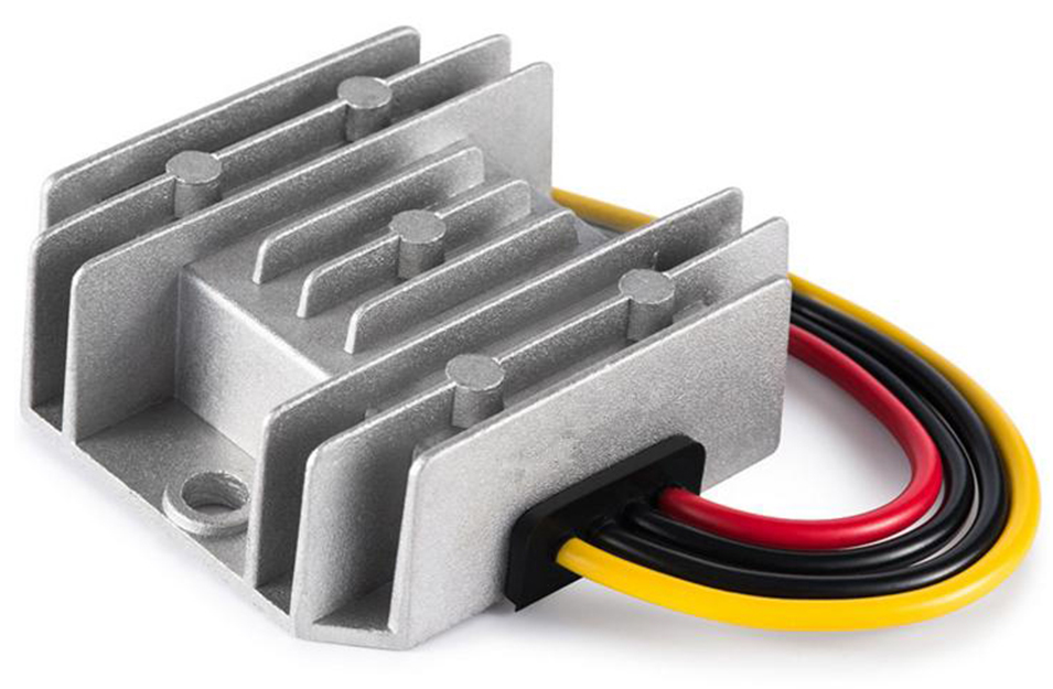
Before testing, define acceptable output voltage, ripple method, load-transition limits and operating conditions. Check the documented input range, actual minimum and maximum load states, startup and restart, and credible changes in downstream capacitance. Use the module’s instructions and an appropriate measurement setup rather than accepting a single steady meter reading.
Keep the distinction between evidence and symptoms. Overshoot, ringing, slow settling or failed startup identifies a condition to investigate; one waveform does not uniquely identify the capacitor as its cause. Input wiring, control mode, loading and measurement technique can also affect the result. Escalate unresolved behavior with the exact configuration and captures.
If a capacitor substitution changes dielectric, package, capacitance under bias or ESR, reopen the affected checks. “Same μF and voltage” is an incomplete replacement rule. For WEHO equipment, obtain the applicable model-level guidance before treating a generic module example as permission to add capacitance.
Send the capacitor network with the converter requirement
Provide the converter model and revision, input/output range, capacitor part numbers and locations, supplier characteristic data, load states and required output limits. Include the proposed layout and any unresolved startup or transient record so the missing evidence can be identified precisely.