



A programmed electronic-load edge is not proof that the same current edge reached the power-supply terminals. Characterize the connecting loop and measure the achieved current together with source-end and load-end voltage before assigning a fast voltage excursion to the supply itself.
Key engineering takeaways
- Name source and load voltage nodes separately.
- Include the complete current-loop inductance and resistance.
- Compare fixtures using achieved current edges, not menu values.
- Identify local capacitance that separates load current from source current.
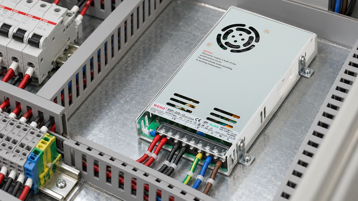
Which event is the fixture applying to the supply?
An OEM validation engineer may change the load leads and obtain a cleaner transient trace without changing the supply. The result can be useful, but it describes a changed test configuration. The engineering decision is whether the fixture delivered the specified event and which voltage belongs to each physical node.
For an RSP-320-12 fixture review, identify the actual source revision, terminals, harness and electronic load. The product reference names the candidate supply. It does not establish a permitted slew rate, a waveform or a particular load instrument's performance.
The existing load-step acceptance guide defines the required event and voltage envelope. This article isolates the fixture contribution: the electrical difference between source and load nodes, and the evidence that the intended edge was actually applied. It does not replace the equipment's transient acceptance specification.
Model the complete connecting loop
For an intentionally simplified two-wire loop, write Vs − Vl = Rloop × i + Lloop × di/dt. Vs is the voltage across the source terminal pair and Vl is the voltage across the electronic-load terminal pair. Define positive current from source to load, and use the same time reference for all quantities.
Rloop includes the relevant outgoing and return-path resistance. Lloop represents the loop inductance, including the effect of conductor arrangement and mutual coupling. It should not be replaced automatically by a guessed inductance per meter or by adding two unrelated single-wire values.
TI's load-transient application report discusses how current-path inductance can change an achieved edge and introduce ringing. Its regulator-board circuit and measurement instructions belong to that application. They are not a ready-made fault or live-wiring procedure for an enclosed mains-powered supply.
The simplified equation omits distributed effects and endpoint capacitance. It is useful for a first fixture comparison only when those assumptions match the question. A real setup can require a fuller model and actual waveform evidence rather than an explanation based on one convenient inductance value.
A hypothetical pair of fixtures with the same current ramp
Assume an ideal source stays at exactly 12.00 V. Both hypothetical fixtures have Rloop = 0.050 Ω and carry an achieved linear rise from 1 A to 5 A in 2 µs. Assume no separate load-end capacitor and neglect other parasitics. These values are illustrative, not RSP-320-12 ratings, measurements or prescribed test conditions.
The current change is 4 A, giving di/dt = 4/2 = 2 A/µs. For fixture A, assume Lloop = 0.10 µH; the inductive voltage during the ramp is 0.20 V. For fixture B, assume 0.50 µH; the corresponding inductive voltage is 1.00 V.
Immediately before the ramp ends, current is approaching 5 A and resistive loss is approaching 5 × 0.050 = 0.25 V. The load-end values approach 12.00 − 0.25 − 0.20 = 11.55 V for A and 12.00 − 0.25 − 1.00 = 10.75 V for B. The assumed source-end value has not moved.
| Hypothetical fixture | Loop inductance | Inductive term during rise | Load voltage just before rise ends |
|---|---|---|---|
| A, 0.050 Ω resistance | 0.10 µH | 0.20 V | 11.55 V |
| B, 0.050 Ω resistance | 0.50 µH | 1.00 V | 10.75 V |
| Either, after settling at 5 A | Unchanged | 0 V when di/dt = 0 | 11.75 V |
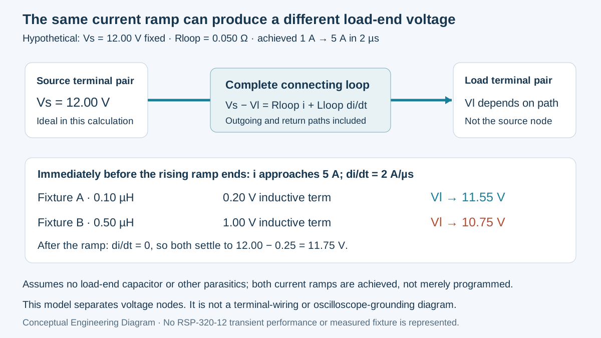
Swipe horizontally on a small screen, or open the full-size diagram.
The 0.80 V difference during the edge comes entirely from the assumed difference in loop inductance. Equal steady-state voltage drop did not make the two fast fixtures equivalent. An idealized instantaneous change in ramp slope also produces a discontinuous inductive term; real edges are rounded by the physical system and should be measured.
For a falling current ramp, di/dt becomes negative. The inductive contribution therefore changes sign under the stated convention. That explains why a load-end upward excursion can appear during current removal without requiring an upward excursion at the ideal source node in this model.
Verify the edge rather than assuming the setting
The calculation assumes that both fixtures actually achieve the same 2 µs transition. A real electronic load may achieve a different edge when the leads change. Its control response and available voltage headroom can interact with the loop, so retain the measured current shape for each fixture rather than comparing only programmed slew settings.
TI's high-slew-rate testing discussion identifies load-path inductance as a limiting factor. Its very fast low-voltage examples are not requirements for this WEHO product. They demonstrate why the intended test event and actual fixture capability must be reviewed together.
Cable length alone is also incomplete. Chroma's electronic-load documentation describes cable designs with different inductance and resistance characteristics. That product-specific example supports recording the actual cable assembly; it does not select a Chroma instrument or transfer its achievable performance to another setup.
Current measurement has its own response. Analog Devices' load-design discussion explains that sense-element parasitic inductance can make its voltage differ from the purely resistive current indication during an edge. Check the current sensor's relevant response instead of treating every displayed spike as actual branch current.
Where does local capacitance change the boundary?
A capacitor at the electronic-load end can supply part of a fast local current change. The load's programmed sink current and the current flowing through the source leads are then different quantities during that interval. Record the capacitor and the location of the current sensor; a valid measurement at one boundary does not automatically describe the other.
Do not add capacitance merely to obtain an attractive transient screenshot. The addition changes the test object and may affect source startup, stability and stored energy. Any such configuration needs the applicable source and instrument documentation, an explicit test purpose and an updated acceptance basis.
| Menge | Physical boundary | Evidence to preserve | Wrong substitution |
|---|---|---|---|
| Source voltage | Defined source terminal pair | Actual voltage trace and node identity | Load-end voltage labeled as source response |
| Load voltage | Electronic-load terminal pair | Trace, loop configuration and load state | Steady cable drop used for the whole edge |
| Source-lead current | Named series path | Measured edge and current-sensor response | Programmed current or local sink current alone |
| Endpoint capacitance | Its actual node and connections | Component identity and test configuration | An unrecorded capacitor added during comparison |
Use instruments and connections appropriate to the voltages and reference relationships. A two-node comparison is not permission to connect ordinary oscilloscope ground clips to arbitrary nodes. Qualified personnel should define the measurement arrangement and applicable equipment energy-control procedures before changing a fixture.
Qualify a fixture change for the intended comparison
- Name the nodes. Record the source pair, load pair, current-sensor location and every local capacitor. Verify that drawing labels match the actual quantities used in the acceptance decision.
- Identify each fixture. Record cables, connectors, return arrangement and characterized resistance/inductance where available. Verify that a guessed value is labeled as an assumption, not reported as a measured fixture parameter.
- Capture the delivered event. Record source voltage, load voltage and relevant current on a suitable common time reference. Verify achieved levels and transition shape before comparing fixtures or supply candidates.
- Evaluate the path contribution. Compare the observed node difference with a justified model. Record uncertainty and omitted effects; verify that unexplained residuals are investigated rather than assigned automatically to the supply.
- Release only the supported result. Record which fixture and achieved event the result covers. Accept the comparison when the required stimulus was achieved and the appropriate voltage node meets its requirement; keep changed-condition and invalid-stimulus attempts distinct.
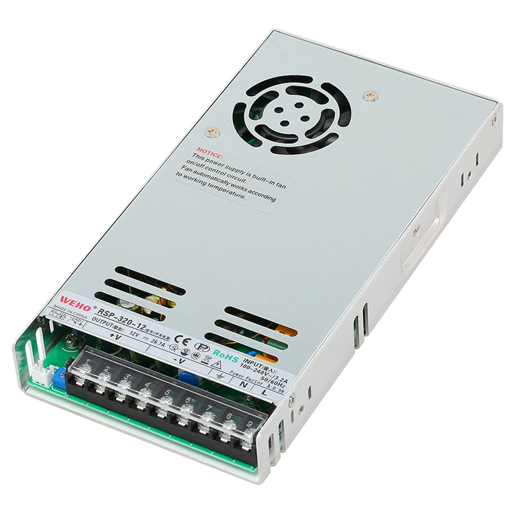
Prepare an RSP-320-12 fixture enquiry
Send WEHO the RSP-320-12 source reference, actual operating conditions, required current event and receiver voltage envelope. Include the fixture drawing and synchronized traces where available. State which voltage node the requirement concerns before asking whether the observed excursion is a source limitation.
Identify the nodes, preserve the actual current edge and document the fixture change before the next comparison. Those actions prevent a cable-dependent measurement from becoming an unsupported statement about product transient performance.
Engineering FAQ
Does programmed slew rate prove the edge applied to the DUT?
No. The achieved transition depends on the load and complete fixture. Measure the relevant current edge and preserve its shape and operating conditions rather than treating a menu setting as an observed stimulus.
Can two fixtures have equal steady drop but different transient drop?
Yes. Equal resistance can produce equal steady-state drop while different loop inductance changes the voltage during a current transition. The example isolates that difference without claiming that either hypothetical fixture represents a WEHO test.
Is electronic-load current always identical to source-lead current?
No. Endpoint capacitance or another local path can supply part of a fast demand. Identify the current boundary and component arrangement before using the load's indication as the source-terminal stimulus.
Does the example predict an RSP-320-12 voltage dip?
No. The source is explicitly ideal and fixed at 12 V in the calculation. The example predicts only the stated lumped path's contribution under assumed achieved ramps; actual source behavior and fixture response require appropriate measurements.



