



An LPV LED driver for an indoor lighting project should follow the lighting circuit, not merely the word “waterproof.” Shop-fitters and display contractors need compatible luminaires, a simultaneous-load schedule and accessible service space. A narrow supply can be useful inside furniture, but a neat-looking installation is not evidence that its voltage, connections or thermal conditions are correct.
Define the lighting zones before selecting the driver
List the shelf runs, sign modules and decorative sections separately. Obtain each lighting product’s required input voltage and permitted control arrangement. Voltage-fed lighting must not be confused with an LED assembly requiring a regulated current source. Similar wattage does not make these two electrical interfaces interchangeable.
Decide which zones operate together and which need separate service isolation. This prevents a furniture layout from becoming an unexplained electrical load. A revised strip length or denser module spacing may change the demand even when the display still looks the same. Keep the fixture schedule connected to the actual purchasing revision.
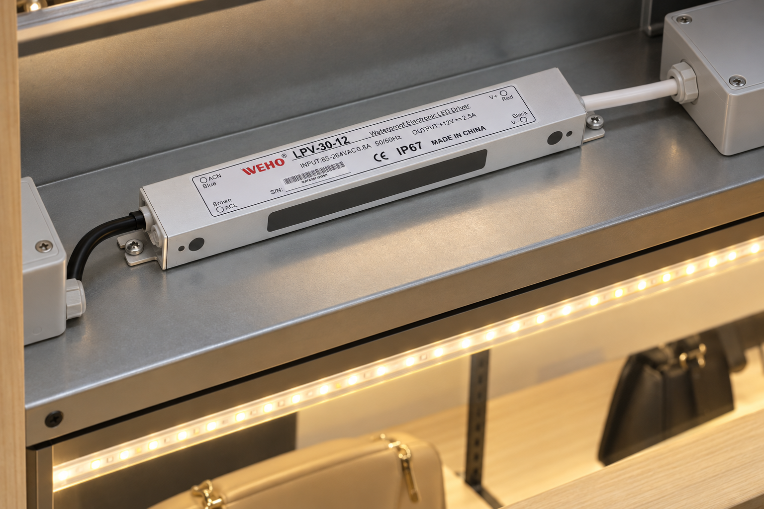
Read the physical specimen and catalogue together
Der official WEHO LPV-30 model table lists LPV-30-12 at 12 V, 2.5 A and 30 W. The photographed specimen is literally marked LPV-30-12, including both model hyphens. Its label reads INPUT 85–264 VAC 0.8 A 50/60 Hz and OUTPUT +12 V with the original DC symbol, 2.5 A. Keep the actual photograph in the sample record rather than redesigning the physical nameplate.
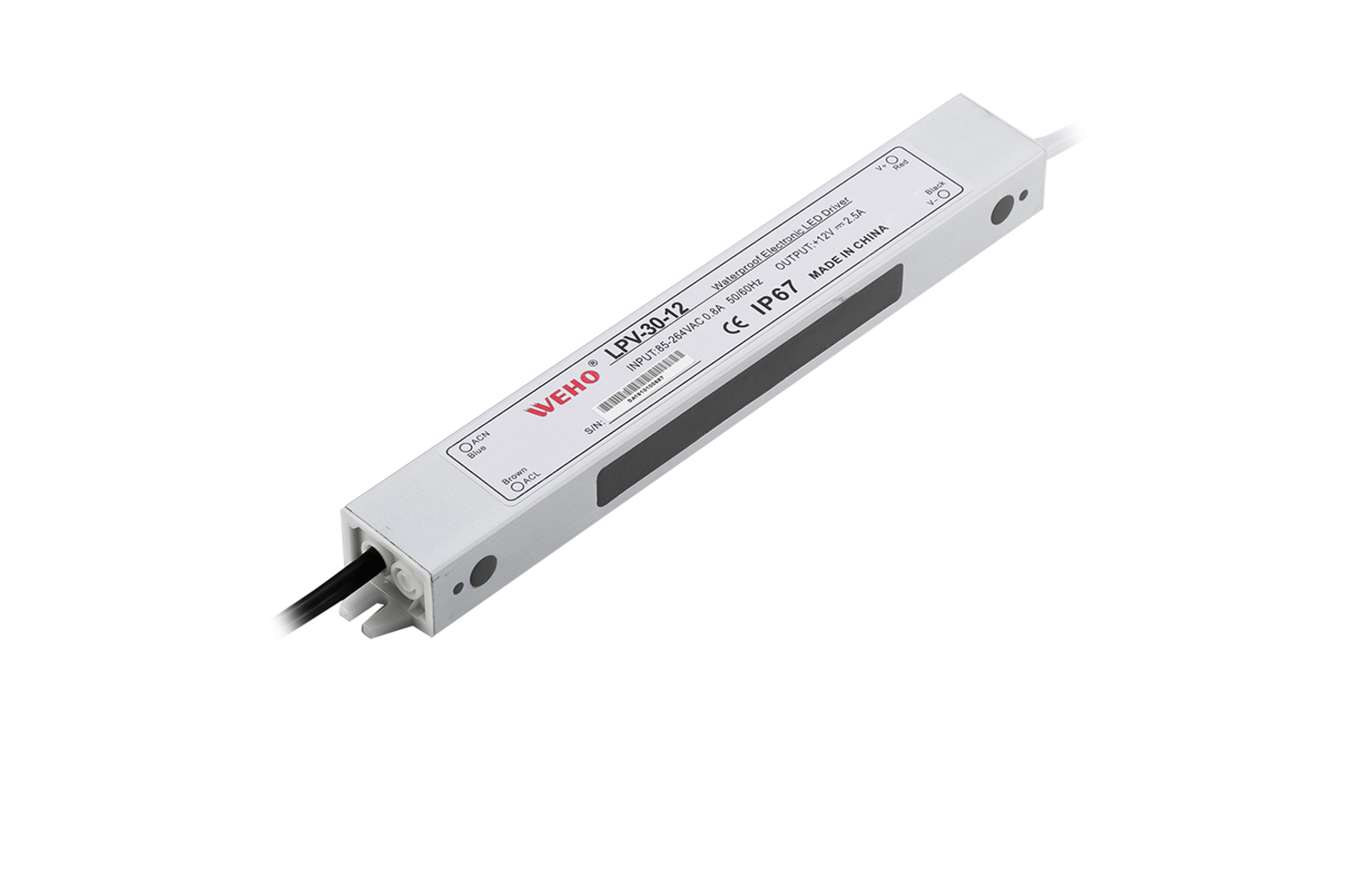
This is a conditional example for compatible 12 V lighting. It is not a replacement for a 24 V branch, a universal constant-current driver or evidence of an external dimming interface. The family page contains broader descriptive language; the exact specimen and matched documentation, not that generic wording, govern the proposed circuit.
Budget simultaneous demand, then evaluate the installation
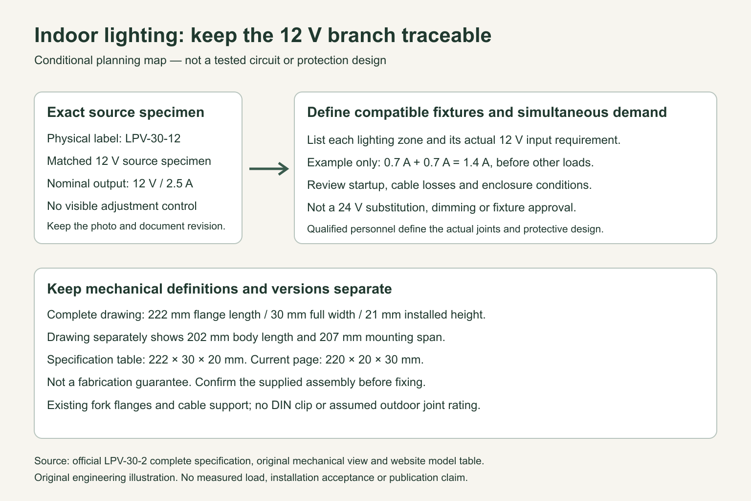
Use the lighting manufacturer’s design data to total the demands that can occur together. Include a controller only if this branch actually supplies it. Ask about startup behaviour and the appropriate design value when only typical consumption is available. Do not assume unused catalogue current is a guaranteed allowance for every operating condition.
As arithmetic only, two compatible 12 V branches specified at 0.7 A each would total 1.4 A before any other load. This does not approve unspecified fixtures or define a universal margin. The engineering team must still assess tolerances, enclosure temperature, operating pattern and any planned expansion.
Consider the voltage at the farthest lighting connection as well as at the source. Cable length, conductor selection and joint losses belong in the project design. This specimen has no visible user-adjustment control; do not plan to compensate for a poorly designed distribution run with an assumed adjustment facility.
Make service space and source revision explicit
The matching complete specification lists 222 × 30 × 20 mm. Its complete mechanical view separately shows 222 mm overall flange length, 202 mm body length, 207 mm mounting span, 30 mm full width and a 21 mm installed-height arrow. The current product page states 220 × 20 × 30 mm. These presentations are not silently combined into one fabrication envelope. Confirm the supplied revision and actual assembly before committing a recess or fixing layout.
The illustrations follow the complete mechanical depiction for visual proportions; they do not certify a production fit. The original unit has existing fork flanges, two factory cable jackets and a long shallow metal enclosure—not a DIN-rail clip. Fixing, cable support and access need to be real parts of the furniture or sign assembly, not a loose supply placed beside the lights.
Allow access to the connection areas without pulling on the factory exits. Keep the driver and service components away from storage items, cleaning routes and preventable impact. A closed void can change the local temperature; source dimensions alone do not prove thermal acceptability or an approved operating orientation.
Do not extend an enclosure marking to the entire project
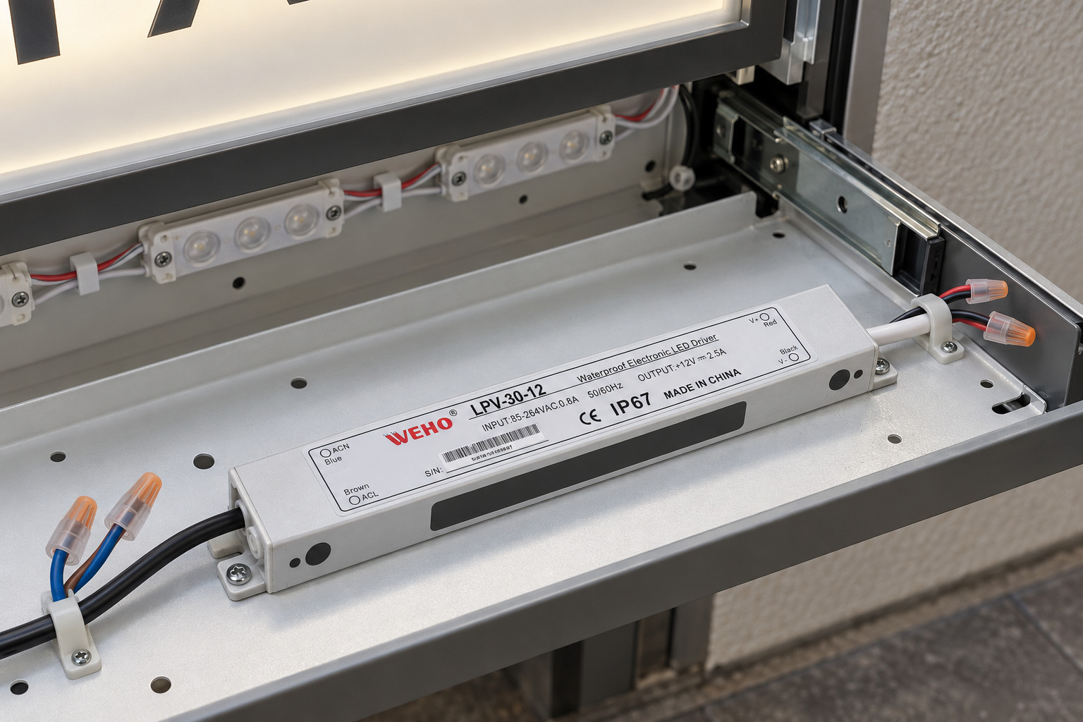
The physical label carries IP67, but the completed system also contains external joints and surrounding equipment. That marking does not establish the protection of an ordinary splice, the furniture or the finished sign. Qualified personnel must specify suitable connections, protective arrangements and access for the actual environment.
The authentic lead identification distinguishes the AC and DC sides. Do not add an invented third factory input conductor or infer an unseen terminal block. Keep the sample’s connection information with the current instructions; this article is a procurement and layout guide, not an electrical-protection or installation procedure.
Hand over a serviceable, traceable project
Give purchasing, assembly and maintenance the same model, sample photograph, document revision and branch schedule. State what can be isolated or replaced without dismantling the display. Record commissioning observations separately from catalogue values. An understandable handoff is more valuable than a drawing that merely says “LED power supply.”
Häufig gestellte Fragen
Can this 12 V example be used for a 24 V lighting run?
No. Match the lighting product’s actual input requirement; do not treat the LPV family name as voltage compatibility.
Does the narrow housing guarantee it fits a particular cabinet?
No. Resolve the documented dimension differences and check the actual supplied assembly, cable space and fixing relationship before fabrication.




