



Key Engineering Takeaways
- A delay between PLC commands does not prove that driver input-current events are separated.
- Compare command, contactor feedback, applied AC and measured input current on one time base.
- The HVG-1800-48 page publishes 55 A cold-start current at 380 VAC, without the pulse duration needed to establish an acceptable separation.
- Release the sequence against recorded electrical events and the selected switching devices’ requirements.
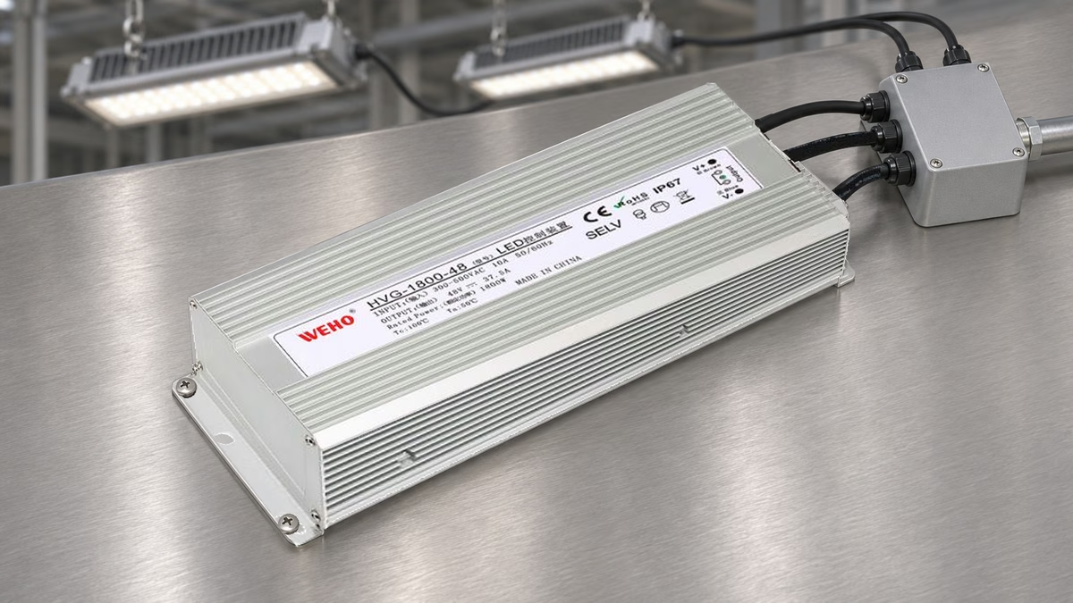
Why the programmed delay is only one part of startup
Two lighting banks can receive different start commands yet draw overlapping input-current events. The command enters a chain that includes the output module, coil circuit, contactor operation and driver energization. A commissioning record must establish where the electrical events occur, rather than assuming that the software timestamps describe them.
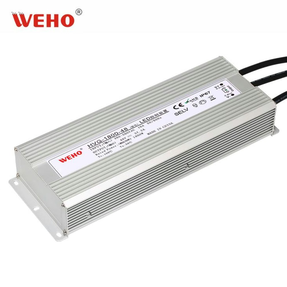
Der HVG-1800-48 high-line LED driver is a useful candidate for this investigation because its published input range is 300–500 VAC. Its table lists 48 V, 37.5 A output and 55 A cold-start input current at 380 VAC. Those values identify the candidate and a test condition; they do not define a permissible contactor, breaker count or stagger interval.
This article addresses one release decision: does the implemented startup sequence separate the measured current events under the conditions the project requires? It does not size the supply network or declare a universal delay between drivers.
Build an event chain with observable timestamps
Define a common origin, such as the first start request, and name each event before connecting instruments. For bank A, record command time, relevant auxiliary-contact transition, AC application at the driver and the beginning and end of the input-current event. Repeat the same definitions for bank B.
A contactor auxiliary contact reports its own mechanical state. Whether its timing represents the relevant main-pole behavior must come from that contactor’s documentation and the measurement plan. Do not relabel auxiliary feedback as “driver AC present” without establishing that relationship.
The current-event boundary also needs a definition. A useful record states the measured current threshold, filtering, instrument range and why that boundary matters to the selected switching or protection device. A software graph whose vertical scale hides a narrow event cannot establish its absence.
Hypothetical commissioning record
Assume two banks have command times of 0 ms and 40 ms. In an illustrative capture, bank A’s observed current interval runs from 22 to 58 ms; bank B’s runs from 50 to 83 ms. These invented timestamps demonstrate the calculation and are not HVG-1800 measurements.
For intervals A and B, the overlap is:
overlap = max(0, min(end A, end B) − max(start A, start B))
The example gives max(0, 58 − 50) = 8 ms. A nominal 40 ms command delay therefore coexists with an 8 ms observed overlap. The record establishes overlap under the stated example conditions; it does not establish whether that overlap is acceptable to any actual device.
| Event | Bank A | Bank B | Evidence |
|---|---|---|---|
| Start command | 0 ms | 40 ms | Controller trace |
| Auxiliary-contact change | 18 ms | 47 ms | Captured feedback |
| Current-event interval | 22–58 ms | 50–83 ms | Illustrative current capture |
| Observed overlap | 8 ms | Interval calculation | |
Uncertainty belongs beside the result. If the two channels do not share a clock, synchronization error can change the apparent overlap. Preserve acquisition settings and channel delay information so a reviewer can decide whether the result resolves the question.

Swipe horizontally on a small screen, or open the full-size diagram.
Choose evidence that can release the sequence
The project needs both an observation and an acceptance rule. “The banks started” is an observation. “The switching device permits these measured events at the required repetition rate” is an acceptance claim that needs the device manufacturer’s applicable information.
Use the following matrix to keep those responsibilities separate. Unknown cells remain open engineering items; they must not become assumed zero delays or unlimited operating frequency in a spreadsheet.
| Question | Required record | Release basis | Owner |
|---|---|---|---|
| Did commands separate? | Controller timestamps | Approved sequence | Controls engineer |
| When was AC applied? | Voltage event and contactor data | Defined event relationship | Electrical engineer |
| Did current events overlap? | Synchronized current captures | Recorded interval definition | Test engineer |
| Is repetition acceptable? | Duty cycle and device documentation | Applicable switching/protection limits | System designer |
The driver’s published 55 A value is insufficient for this final row. Pulse duration, actual conditions, repetition and the selected device’s response remain relevant. Multiplying 55 A by the number of units produces an arithmetic result, not an approved electrical coordination study.
Capture the sequence without losing the operating conditions
- Freeze the configuration. Record the exact driver suffix, quantity, contactor and protection-device references, wiring revision and controller program version. Photograph identification labels while the system is in a suitable de-energized state. This makes the trace attributable to the configuration being released.
- Define each channel. Write down which signal establishes command, feedback, applied AC and current. State where each measurement occurs and identify the instrument/probe combination. Use appropriately rated measurement equipment and a qualified electrical test procedure for the actual supply system.
- Establish the time base. Confirm the channels share an acquisition clock or document synchronization uncertainty. Capture pre-trigger information so an early event does not disappear when the second bank starts. Keep raw traces as well as screenshots.
- Record the starting state. Note input voltage, connected load, ambient condition and the preceding off interval. Ask the driver supplier which initial conditions apply to its published cold-start figure. Do not treat every restart as an equivalent cold start.
- Run the approved sequence. Compare the command gap with the measured event gap. Record a negative gap as overlap, using the stated interval definition. Repeat only within the test procedure and switching-device limits; do not invent a high repetition rate to obtain more samples.
- Release or hold by evidence. Compare the actual traces with the project’s documented acceptance rules. If the result is inconclusive, identify the missing timing, measurement or switching-device information. Increasing the software delay may be a trial change, but the changed sequence still needs verification.
For floating voltage measurements, the probe reference and instrument architecture matter. Tektronix explains why ordinary grounded oscilloscope references cannot simply be connected to arbitrary floating points; follow the applicable instrument and probe instructions when planning the capture. Tektronix floating-measurement guidance
Send a timing evidence package with the technical inquiry
Review der HVG-1800-48 input specifications and send WEHO the actual input range, quantity, switching sequence, preceding off interval and current captures. Ask which current revision and startup conditions apply, and whether additional inrush waveform information is available. Include the switching-device references so the inquiry has a specific system boundary.
Download the startup event recording sheet to keep commands and measured electrical events together. Its example timestamps are instructional; replace them with attributable records before using it for release.
Engineering FAQ
Does a 100 ms PLC delay guarantee separate driver inrush events?
No. A programmed delay separates commands; the resulting electrical events require measurement or applicable timing evidence. Record the full event chain and the uncertainty of the time comparison before deciding whether the actual separation satisfies the project.
Can an auxiliary contact replace an AC measurement?
Only when its relationship to the relevant main-pole event is established for the chosen contactor and purpose. An auxiliary transition is not automatically the instant AC reaches the driver. Keep the signal’s actual meaning in the test record.
Can the 55 A published value determine a safe stagger interval?
No. The HVG-1800 table’s cold-start figure does not supply a pulse duration or a system acceptance rule. Request the missing waveform conditions and use the selected switching and protection devices’ applicable requirements.
What should change after the controller program is edited?
Update the program reference and verify the affected startup sequence again. Preserve the earlier capture for comparison, but do not use it as evidence for a timing configuration it did not test. The release record should identify the exact implemented version.



