A PWM-to-DC converter is suitable for power-supply control only when both sides of the interface are defined. Check the controller’s logic levels and frequency, the converter’s output range and loading, and the exact supply’s documented programming input. A filtered PWM average is not automatically a compatible 0–10 V command, and a programming input is not a DC power-output terminal.
On this page
This guide helps an OEM decide whether an external control chain can meet a setpoint requirement. It does not establish PWM, analog programming or remote-trim capability for any WEHO model. If the selected supply lacks a documented control interface, resolve that first rather than attaching an adapter.
Separate the command path from the energy path
A microcontroller may encode a requested operating point in duty cycle. An interface converts that information into an analog voltage, which a compatible supply interprets according to its programming law. The load receives power from the supply’s output stage. These are different paths with different voltage, current and reference requirements.
Do not infer behavior from similar labels such as PWM dimming, voltage programming, trim or enable. One port may expect a pulse train, another an analog voltage, and another a resistance. Even where two inputs use volts, their reference connection, polarity, permitted range and safe default can differ.
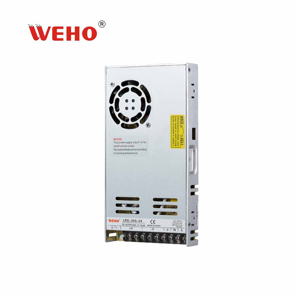
Use a real candidate to screen the interface before adding a PWM-to-DC board. The WEHO LRS-350-24 product information και LRS-350 specification identify an adjustable DC output, but the reviewed public documents do not specify a PWM or 0–10 V remote-programming input. Do not connect a command signal to the voltage-adjustment point or infer remote control from the ADJ marking. Obtain a documented interface or select a supply that explicitly supports the required command.

Write a complete interface map
| Boundary | Define before selection | Acceptance evidence |
|---|---|---|
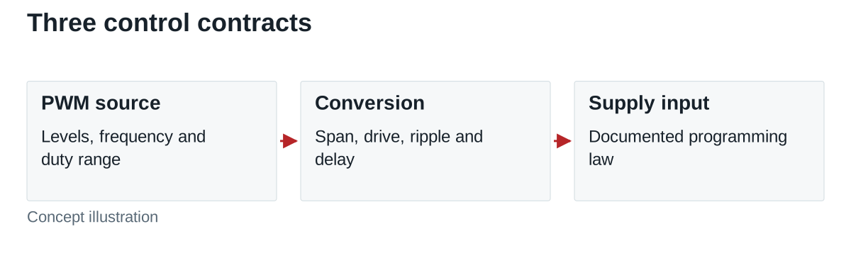
| Controller to converter | High/low levels, frequency, duty range, jitter and drive loading | Compatible input thresholds at relevant voltage and temperature |
| Converter output | Span, offset, gain accuracy, ripple, impedance and source/sink limits | Measured command under actual programming-input loading |
| Supply programming port | Transfer law, reference, isolation, absolute limits and input impedance | Exact model instructions and interface limits |
| Whole equipment | Setpoint tolerance, response time, startup and loss-of-signal behavior | End-to-end tests with the intended load and sequences |
State whether percentages refer to converter full scale, supply output full scale or the requested operating value. A small percentage at one stage can consume a substantial share of a narrow equipment tolerance. Include measurement uncertainty rather than assigning the entire allowance to nominal component accuracy.
Calculate scaling before choosing a converter board
In an idealized example, PWM switches between exactly 0 V and 5 V. Its average is duty cycle multiplied by 5 V, so 40% duty gives 2.0 V. If a hypothetical compatible supply needs a 0–10 V command, a unity-gain averaging stage cannot reach its full command range. A separate, correctly designed scaling stage would be necessary.
Assume that supply’s stated programming law maps 0–10 V to 0–30 V output. A 4.0 V command represents 12 V output. Starting from the 2.0 V PWM average would require an ideal gain of two. None of these assumed spans describes a WEHO product; the example shows why the actual transfer law must precede hardware selection.
Offset matters too. Under the same hypothetical law, a 0.10 V command error corresponds to 0.30 V output error. This does not include the supply’s own accuracy or load effects. Record the complete error allocation and verify the result at the load, especially near the lowest useful setpoint.
Trade ripple against delay deliberately
Analog Devices’ PWM-to-analog discussion explains why a passive filter’s ripple, output impedance and settling behavior matter. A buffer can address output loading, but it does not remove the filter’s time response. Its examples concern particular circuits and should not become an assumed response specification for an external adapter.
For a separate first-order calculation, take R = 10 kΩ and C = 1 μF. The time constant is 10 ms, and the cutoff is approximately 15.9 Hz. Following an ideal step, the remaining error falls below 1% after about 4.605 time constants, or 46 ms. This is an ideal first-order settling illustration, not a complete component recommendation; residual PWM ripple also depends on the carrier frequency relative to the filter cutoff.
The total command-to-load delay also includes converter updating, buffering, the supply’s control response and the connected load. A filter that settles in 46 ms cannot establish a 46 ms equipment response by itself. Measure ripple and settling separately, with a defined bandwidth, command step, acceptance band and actual interface load.
Consider the conversion architecture
A duty-cycle measuring DAC is another architecture. The LTC2644 Rev. B datasheet describes a device that measures PWM timing and updates a voltage DAC. That example demonstrates that PWM-to-voltage conversion need not be a passive averaging filter. It does not qualify the part, a ready-made board or its output span for a particular power-supply port.
Compare candidates using the required input frequency, update behavior, output drive, reference accuracy and idle-state handling. Check their supplies and startup ordering as part of the interface. Isolation is a separate requirement: a low-voltage control signal does not prove that connecting the controller reference to the supply port is permitted.
Test startup and missing pulses
Define the requested behavior before firmware starts, during reset, with a disconnected cable, at constant high or low input and when PWM stops. A converter may hold, drift, disable or choose a defined idle state; the exact behavior comes from its specification. The resulting supply output must meet the equipment requirement in each case.
Use endpoint, intermediate and repeated-step tests. Confirm monotonic command direction, settling, output ripple and absence of unwanted excursions. Retest after changes to PWM frequency, converter gain, filtering or the selected supply. An unloaded adapter voltage measurement is insufficient when the programming port changes its loading.
Request the model interface before design release
Provide the proposed WEHO model, desired output range, available PWM signal and acceptable error, ripple and delay. Ask which control function, if any, is documented for that exact configuration. Keep any external converter qualification separate from the supply’s own supported features.