A heating command shows what the control system requests; it does not prove that the heater receives the intended current. Compare command state and actual load-current evidence before changing PID settings or replacing the controller.
- Record the controller request and the delivered heater current separately.
- Consider switching-device, heater, supply and measurement faults.
- Treat external protective functions as separate from ordinary temperature regulation.
Why does the output indicator not prove heater operation?
An output indicator represents a control state, not a direct measurement of every downstream component. A command can be present while a heater circuit is open, or absent while a failed switching path continues conducting. The exact interpretation depends on the supplied controller and external switching arrangement.
For an OEM integrating a TX4-S temperature controller, verify the ordered output type and applicable connection diagram. Do not infer a current-monitoring input, heater-break alarm or independent shutdown capability from the controller's front-panel appearance.
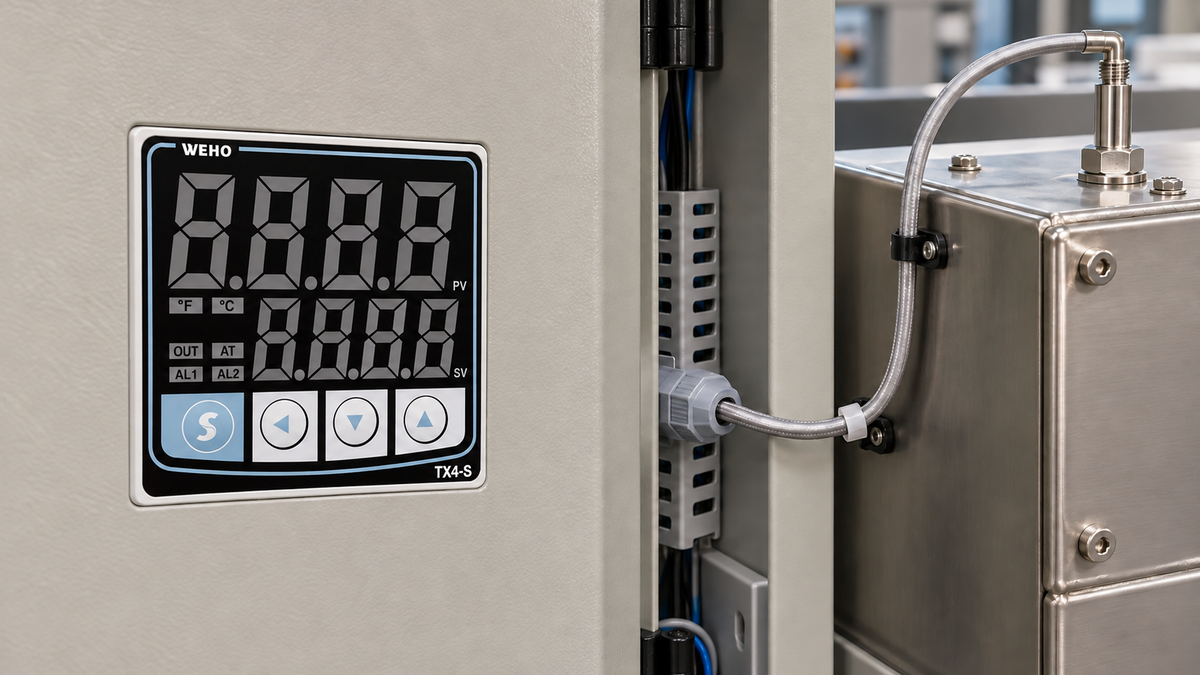
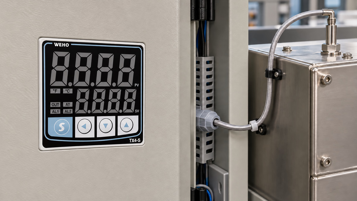
The application scene shows the controller's panel context. Its inactive display does not establish a measured heater current or an actual fault condition. The technical state table below is a separate conceptual example, not evidence that TX4-S provides built-in monitoring for every listed state.
This distinction helps avoid unnecessary tuning changes. If the controller requests heat but a disconnected heater draws no current, altering the proportional band cannot repair the open circuit. If current continues when heat is not requested, a different and potentially more serious path needs investigation under the equipment procedure.
What can a command-current state table establish?
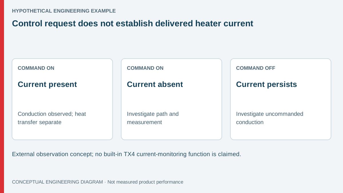
A state table compares two independent observations and identifies the next diagnostic question. It does not prove a unique failed component. A missing current reading may come from the load path, the supply state or the measuring system itself.
Consider a hypothetical resistive heating branch that draws 4.0 A during a valid ON interval. An externally established observation threshold of 0.2 A is used only to distinguish substantial conduction from the example's measurement noise and expected residual behavior. That threshold is not a TX4-S or universal heater-protection setting.
When the command is ON and measured current is 4.0 A, the record supports that current flowed in the measured branch. It does not prove that heat reached the workpiece correctly. When the command is ON and current is below the chosen threshold, the branch needs investigation without assuming the controller is defective.
When the command is OFF and substantial current remains, establish the actual switching topology and source paths. Solid-state switching devices can fail conducting; other paths can also exist. Do not use this table as an instruction to work on an energized heater or as a substitute for the machine's protective design.
| Observed command | Observed branch current | Initial interpretation | Required distinction |
|---|---|---|---|
| ON | 4.0 A in the example | Current reaches the measured branch | Heating effectiveness and correct load identity |
| ON | Below example 0.2 A threshold | Expected conduction not established | Open heater, missing source, switch path or sensor issue |
| OFF | Below the chosen threshold | No substantial current observed by this method | Isolation and absence of voltage remain separate |
| OFF | Substantial current persists | Uncommanded conduction requires investigation | Switch failure, alternate path or incorrect state measurement |
What external switching evidence is needed?
Identify whether the actual system uses a relay contact, an SSR drive and external SSR, or another documented arrangement. A drive signal and a load-power contact have different ratings and roles. Applying a load directly to an unsuitable signal output is not justified by a generic wiring example.
Le official TX4 manual provides the starting point for the relevant controller arrangement. Match it to the delivered variant and the switching component's own documentation. Do not assume all ordering combinations shown in a reference diagram are supplied or supported.
OMRON's SSR precautions explain why a conducting failure mode must be considered in a heater system. This external principle does not establish that a WEHO controller includes a particular detection or protective function. The equipment designer must assess the complete arrangement.
Record alternate power sources, shared branches and current-sensor location. A sensor around a common feeder may include more than the heater under investigation. A current transformer or clamp around both outgoing and return conductors can also produce a misleading result, depending on the method. Follow the instrument's applicable instructions.
How should timing be handled for time-proportioned outputs?
A time-proportioned command intentionally alternates ON and OFF intervals. A slow meter may average those intervals, while a spot observation may catch only one state. Compare current with the command on an appropriate common time reference rather than treating an average display as continuous conduction.
For a hypothetical DC heating-current waveform over 10 seconds, suppose current is 4.0 A for 3 seconds and zero for 7 seconds. Its average current over that simplified window is 1.2 A. Its RMS current is 4 × √0.3 = 2.19 A, approximately. Those quantities answer different questions. For an AC heater, distinguish signed current from its RMS or magnitude envelope rather than applying the DC average directly.
- Identify the actual control-output cycle and downstream switching method.
- Select measurement equipment with suitable current, voltage and timing capability.
- Record command state and branch current over complete relevant intervals.
- Separate ordinary OFF-state residual behavior from substantial conduction using a justified method.
- Investigate discrepancies under the equipment's isolation and fault-response procedure.
Qualified personnel should establish the setup and control any consequences of simulated states. A zero current observation does not prove electrical isolation or absence of hazardous voltage. Never use an output indicator or a current threshold as the sole basis for accessing a circuit.
What should a supplier receive before the controller is replaced?
Provide the controller variant, output arrangement, switching-device identity and a synchronized command/current record. Include supply state, load identity and the measurement boundary. This distinguishes a controller request problem from a downstream power-delivery problem without forcing an early component diagnosis.
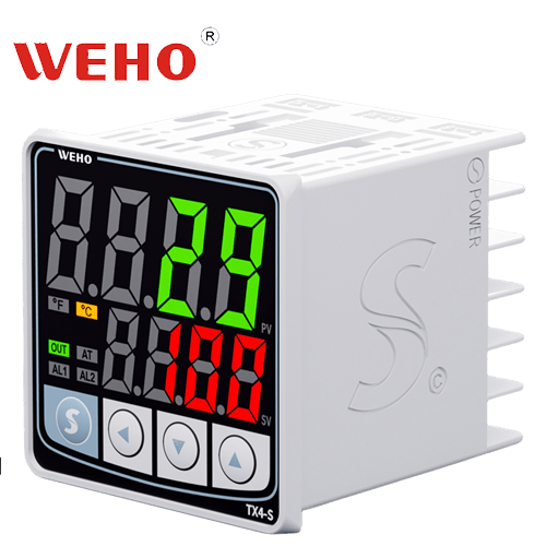
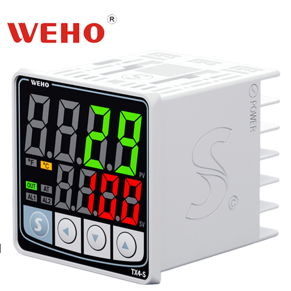
Le TX4-S product entry helps identify the supplied model. Request applicable documentation if the output configuration is unclear. The article does not promise a built-in current-sensing function, safety-rated shutdown or compatibility with an unspecified SSR.
Keep the actual process response in the record as another channel. Current may flow normally while a loose heater, changed thermal contact or displaced probe causes poor temperature behavior. Electrical delivery and useful heat transfer need different evidence, and a tuning change should not conceal a mechanical or sensor problem.
A current sensor's threshold and delay should be matched to the intended state distinction. A threshold selected only to avoid nuisance indications can hide a meaningful low-current failure, while one set below ordinary residual behavior can create false alarms. Establish the actual measurement capability and equipment requirement before choosing either value.
The record should also distinguish one failed element from several parallel heaters. Total branch current may remain substantial after one element opens. A simple current-present decision can therefore miss a partial loss of heating capacity unless the monitoring boundary and acceptance rule address it.
Prepare a TX4-S heating-path review
Send WEHO the ordered controller details, applicable connection diagram, load and switching information, and the observed state table. State whether the discrepancy concerns the command, electrical delivery or process temperature. This supports a focused technical discussion while leaving protective design and fault handling with the responsible equipment team.
Frequently asked questions
Does an ON indicator prove that the heater receives power?
No. It indicates a control state according to the device's design. The downstream switching path, supply and heater must be checked with suitable independent evidence.
Can current flowing with an OFF command be ignored as normal leakage?
Not without a justified assessment. Expected residual behavior and substantial uncommanded conduction must be distinguished using the actual switch, load and measurement specifications. Follow the machine's fault procedure.
Does zero measured current prove safe isolation?
No. Current observation is not an absence-of-voltage test or an isolation procedure. Electrical access requires the equipment's established energy-control and verification method.
Should PID tuning be changed when commanded heat produces no current?
First establish the electrical delivery path and measurement validity. Tuning cannot repair an open heater or missing power source, and changing settings may obscure the original diagnostic evidence.