



To commission PLC analog control of a power supply, confirm the interface, measure the command at the supply, and check the resulting output under the required operating conditions. The PLC’s displayed setpoint alone cannot show whether the correct signal reaches the supply or the intended voltage reaches the load.
This checklist uses the WEHO SE-1500-30 as an interface example. It takes an OEM controls engineer from document checks to fault isolation and a repeatable acceptance record. Use the confirmed instructions for the exact controller and supply revision before making the connection.
Confirm what the SE-1500 interface supports
The WEHO SE-1500-30 product information and SE-1500W specification sheet list external 0–5 V / 0–10 V control for voltage and current. The published control diagram identifies V and A programming positions, GND, +5 V, +12 V and OFF connections.
Before wiring, obtain the terminal assignment and configuration instructions applicable to the supplied unit. Confirm which programming input to use, how its range is selected, and how local adjustments interact with external control.
A 10 V command is not automatically a 30 V output command. The output adjustment range and the analog command-to-output relationship are different specifications. Confirm the transfer function; the sheet’s voltage-accuracy figure alone does not define the accuracy of the complete PLC-to-output path.
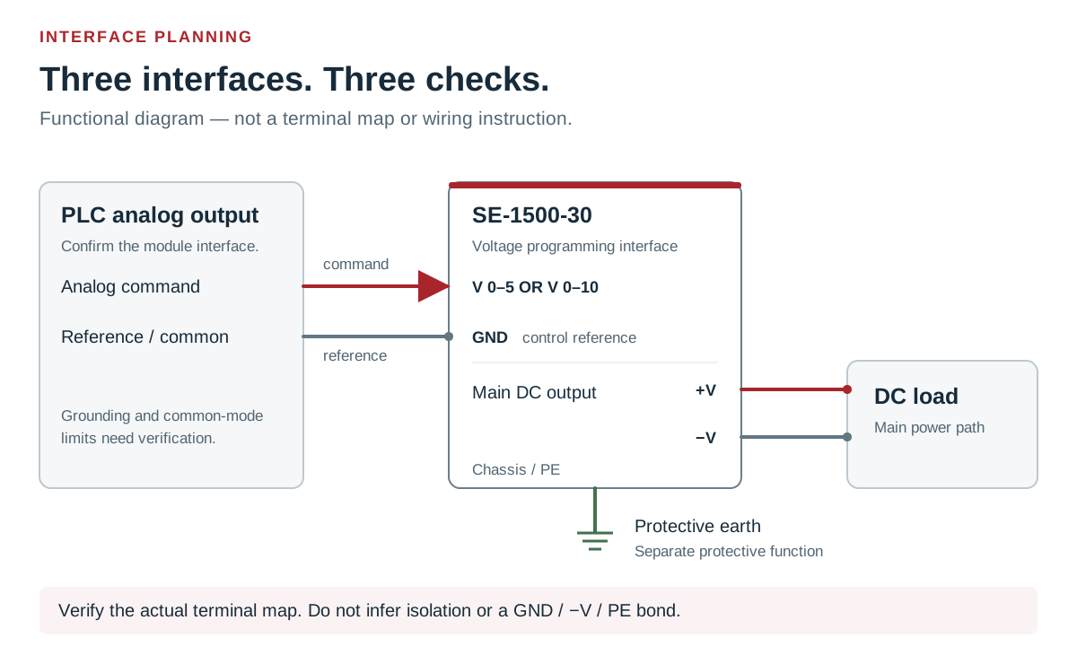
Document the controller and supply as one interface
Use one record for the PLC output module, supply suffix and hardware revision. The same “0–10 V” marking on both devices does not settle input loading, signal reference or inactive-state behavior.
| Check before connecting | Record or obtain |
|---|---|
| Command range | PLC voltage-output mode and raw-code scaling; supply input range, exact terminal and permitted limits. |
| Electrical loading | Supply control-input impedance or input current; PLC module’s permitted load and any required output-side power supply. |
| Signal reference | Specified return terminal, isolation boundaries and allowable reference-to-earth voltage. |
| Control configuration | External-control selection and the role of local voltage/current adjustments. |
| Output relationship | Documented endpoints, transfer function, tolerance and response conditions for the controlled quantity. |
| Inactive states | Required behavior during PLC STOP, loss of controller power, an open control wire and recovery. |
The AutomationDirect F2-02DAS-2 manual, chapter 13, for example, specifies output loading, range selection, isolation and update conditions separately. Check equivalent fields for the actual module; this example does not establish its compatibility with the SE-1500.
Keep protective earth, DC output negative and signal reference distinct in the wiring record. Connect them only as the applicable equipment documents require. Supply input/output insulation data does not establish isolation of the analog interface.
Measure the command and output at separate points
Once the interface is confirmed, use a suitable test load before connecting the process load. Record input power, ambient temperature, load, control range and instrument uncertainty. Follow the equipment’s installation and isolation procedure for wiring and measurement access.
- Check the PLC output. Compare its measured voltage with the intended command, using the output module’s specified reference.
- Measure at the supply control input. With the interface connected, measure between the confirmed programming terminal and its specified return. Record what the supply receives, not just the PLC register value.
- Measure the main DC output. Record voltage, current and operating mode. If the requirement applies at the load, also measure there so distribution loss remains separate.
- Repeat over the required operating window. Include low, intermediate and high operating setpoints, approaching the same points from both directions. Use endpoints only when the confirmed interface and load limits permit them.
For a voltage-control check, verify that current limiting is not setting the observed voltage. For a current-control check, use a load and voltage condition that permit current regulation. An arbitrary load need not draw the commanded current.
Use the measurements to choose the next check
Compare readings at the same setpoint and operating condition. The patterns below identify where to investigate; they do not establish a fault cause or justify changing the wiring without its applicable instructions.
| What you observe | Next check |
|---|---|
| PLC output voltage differs from the intended command | Verify the selected range, raw-code conversion and output-module configuration. Confirm the measurement reference before adjusting scaling. |
| Command is correct unloaded but changes when the interface is connected | Compare input loading with the output-module rating; check the assigned terminals, signal return and any required module power. |
| Command at the supply is correct, but its output differs from the expected value | Check the confirmed transfer function, local/external-control settings and operating mode. Record load and current-limit conditions. |
| Supply-terminal voltage meets the requirement, but load voltage does not | Record both locations and their returns, then assess the distribution path under the same load. |
Separate command-path error from output error
Hypothetical calculation—not an SE-1500 calibration result. Assume a confirmed linear interface maps 0–10 V command to 0–30 V output, so its gain is 3 V/V with zero offset. The required output is 15.00 V, giving an intended command of 5.00 V. Assume a steady test load within the voltage-regulation region and compare measurements after settling.
| Quantity | Illustrative value |
|---|---|
| Intended command | 5.00 V |
| Command measured at the supply input | 4.96 V |
| Expected output from the measured command | 3 × 4.96 = 14.88 V |
| Measured main output | 14.84 V |
| Total difference from the intended output | 14.84 − 15.00 = −0.16 V |
The command-path contribution is 3 × (4.96 − 5.00) = −0.12 V. The remaining difference is 14.84 − 14.88 = −0.04 V. Together they account for the −0.16 V total.
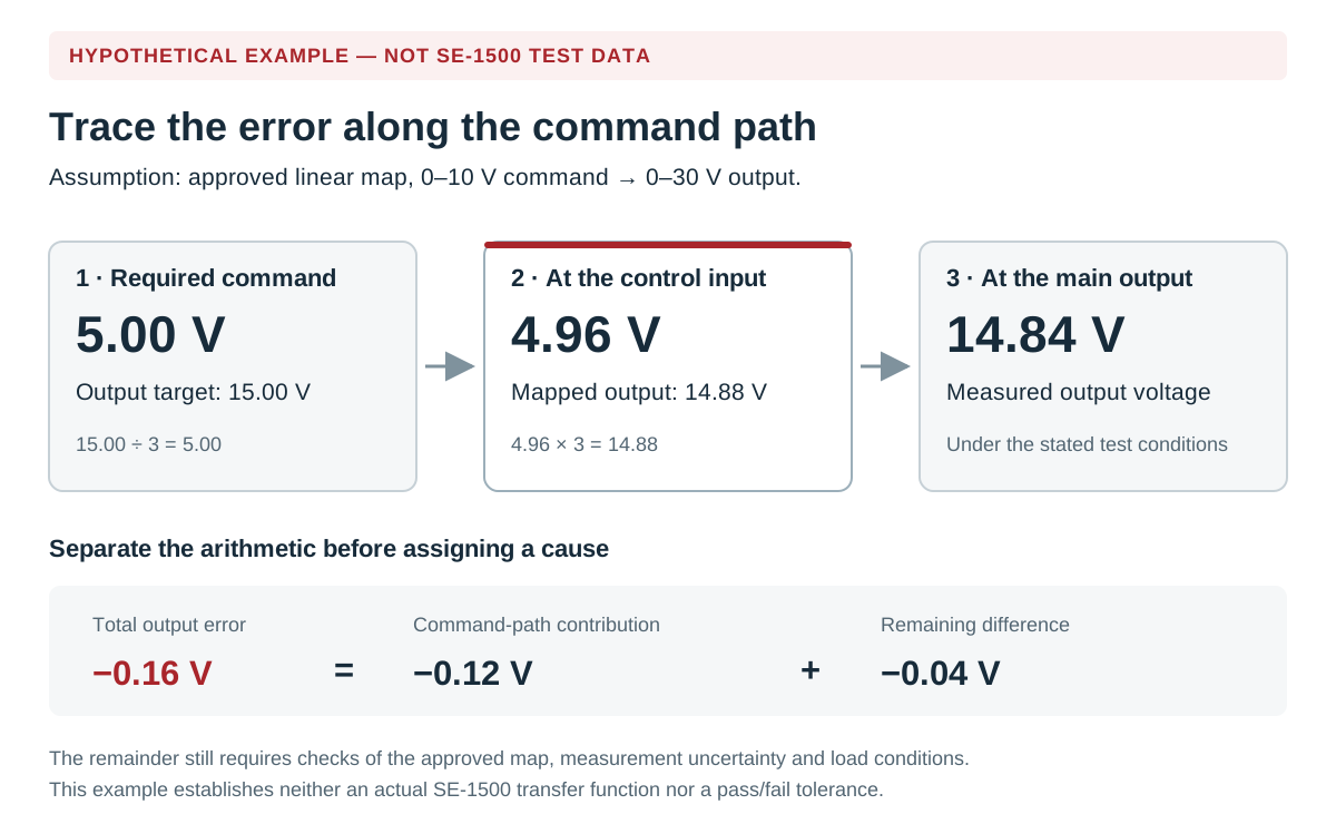
Use the actual transfer function and measurement uncertainty before allocating an error this way. The remaining −0.04 V is a residual difference, not proof of a supply defect. Compare the final output with the project tolerance, and correct interface problems before applying any scaling adjustment.
Check control loss and restart separately
A PLC STOP state, loss of PLC power and a disconnected analog conductor can produce different electrical conditions. Verify each required state under a controlled test plan; do not assume all three become a valid zero-volt command.
The SE-1500W sheet describes the remote-switch function as output enabled by default, with a 3–12 V high-level command disabling it. That statement concerns the remote-switch interface. It does not specify the behavior of an open analog input, and it does not make the OFF function a safety isolation device.
Observe the actual command and main output during each transition. If steady points pass but startup overshoots, retain the failure and verify the proposed control-state or sequencing correction before release.
Make a release decision another technician can repeat
Set acceptance limits before collecting results: final error, allowed excursion and settling time, plus required behavior when control is lost and restored. Choose enough operating points to cover the equipment’s actual window; five points are not a universal pass criterion.
| Test point | Record for each run | Acceptance basis |
|---|---|---|
| Steady setpoint | PLC value; control-input voltage; DC voltage/current; load; approach direction. | Project tolerance with measurement uncertainty. |
| Command change | Start/end commands, output excursion and time to enter the specified band. | Allowed excursion and settling time for the equipment. |
| Load change | Same command before/after the defined load change; control and output measurements. | Required behavior within the documented output envelope. |
| Loss and restoration of control | Controller state, physical command, main output and whether operation restarts. | Documented machine-state requirement and recovery procedure. |
Release only the tested configuration and operating window. Attach controller settings, document revisions and raw results. Leave missing evidence as pending and preserve failed results with their correction and retest record. Repeat affected checks after changes to the controller program, module, supply revision or wiring.
Open the blank PLC–power-supply acceptance record to record the confirmed interface, test conditions and measured results.
Request the interface details for your PLC project
Send WEHO the PLC analog-output module number, proposed control range, required voltage/current window, load type and restart requirements. Request the applicable एसई-1500-30 terminal assignment, transfer function, input-loading limits and inactive-state behavior for your unit.





