



Key Engineering Takeaways
- Measure the battery-side and inverter-terminal voltages under matching load conditions when investigating input sag.
- Separate a falling source voltage from the voltage lost through the complete positive-and-return branch.
- Use current and simultaneous voltage differences to estimate branch resistance and loss; an unloaded reading cannot establish loaded performance.
- Check the exact ordered inverter's operating limits and protection behavior before assigning a cause to an output interruption.
Why can the battery reading look acceptable while the inverter input falls?
The inverter may receive less voltage than a battery monitor reports because current passes through conductors, connections and protective components between the two measurement points. The source voltage can also fall under load. An OEM diagnostic record must distinguish those effects before replacing the inverter or declaring the battery healthy.
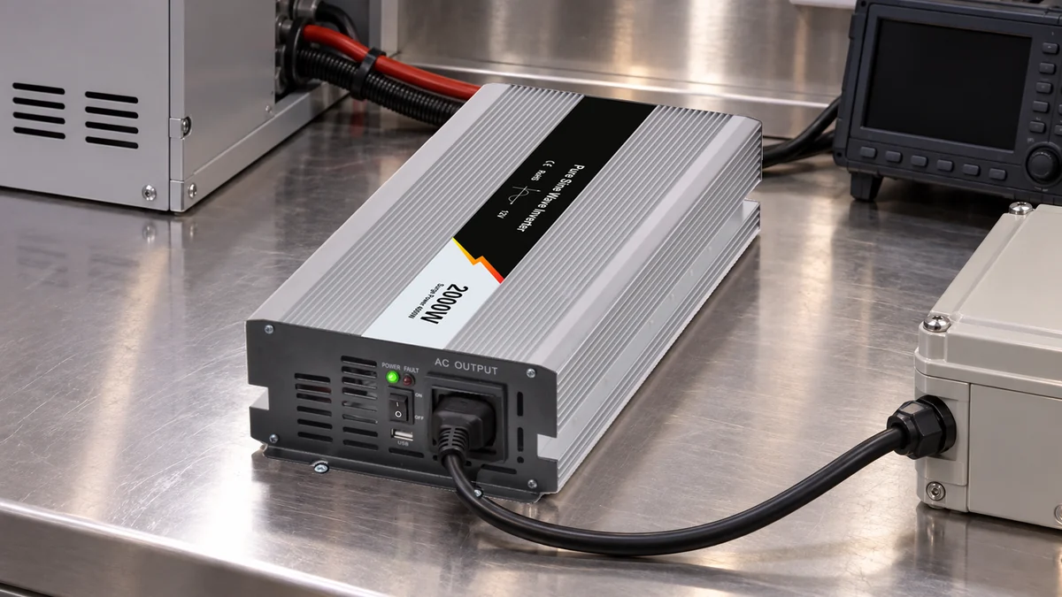
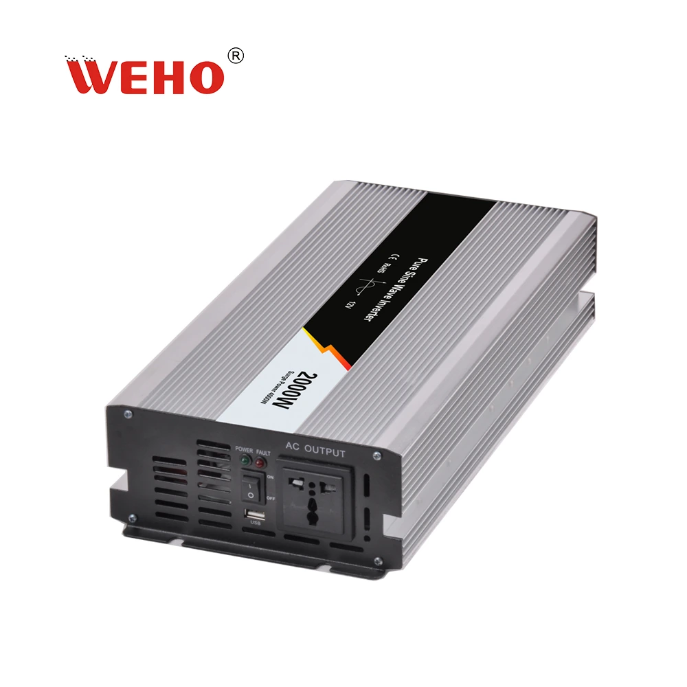
The WHP-2000 inverter family information provides the product reference for this method. The photographed unit retains its original 12 V marking; it is not relabeled as another input option. Its appearance does not establish the ordered AC output or qualify a particular battery installation.
This article addresses the measurement boundary between the battery and inverter. It is distinct from choosing a nominal input version, measuring the AC waveform or predicting battery runtime. The useful output is a synchronized voltage-and-current record that helps the equipment engineer decide which part of the DC system needs investigation.
Where should the measurement boundary begin and end?
Define one voltage at the intended battery source boundary and another at the inverter's actual DC input boundary. Include the complete current path between them. A record that compares a battery-monitor display with a later handheld reading may describe different moments rather than a real distribution loss.
The manufacturer's WHP-2000W document identifies the product family and describes input protection features. It does not make this worksheet a controlled installation instruction or supply a verified protection threshold for every delivered option. Obtain the operating and protection information applicable to the ordered unit before interpreting a trip.
For an assembled system, record where each voltage is sensed: battery posts, a distribution bus, a disconnect output or the inverter input connections. Those locations are different electrical boundaries. A monitor connected upstream of a connector cannot report the drop across that downstream connector unless it has a separate measurement arrangement.
Measurement equipment and connections must be suitable for the circuit's voltage, available fault energy and transient conditions. Qualified personnel should establish the measurement arrangement under the equipment's approved procedure. This article does not authorize improvising exposed probes around a high-current battery or bypassing a protective component to see whether the symptom disappears.
How can you separate source sag from branch drop?
Compare the two voltages at the same operating point, then relate their difference to the branch current. The unloaded source-to-loaded-source change describes one aspect of source sag. The simultaneous source-to-inverter difference describes loss between the selected boundaries. Neither result alone identifies a specific failed part.
Hypothetical Loaded-Input Example
Assume an invented 12 V-class equipment test records a battery-boundary voltage of 12.2 V, an inverter-terminal voltage of 11.5 V and branch current of 50 A at the same stable operating point. Before the load event, the source-boundary reading was 12.6 V. These values are calculation inputs, not measurements of a WHP unit or a proposed acceptance limit.
| Quantity | Calculation | Illustrative result | Interpretation |
|---|---|---|---|
| Source change | 12.6 − 12.2 V | 0.4 V | Change at the selected source boundary |
| Loaded branch drop | 12.2 − 11.5 V | 0.7 V | Difference between simultaneous loaded boundaries |
| Estimated branch resistance | 0.7 V ÷ 50 A | 0.014 Ω = 14 mΩ | Combined path between those boundaries |
| Estimated branch loss | 50 A × 0.7 V | 35 W | Electrical loss at this operating point |
| Inverter-boundary DC power | 11.5 V × 50 A | 575 W | DC input power, not AC output power |
The resistance estimate includes whatever lies between the defined voltage boundaries, including both conductors and their intervening components. It is not automatically the cable's copper resistance. An unexpected value can come from a contact, a fuse assembly, a disconnect, a conductor or several contributions together.
The 35 W estimate is also a total, not a temperature prediction or a statement that all the heat occurs at one connection. If a large share is concentrated in a small contact, the local condition can differ from a distributed conductor loss. A separate inspection and appropriate measurements are needed to locate the contribution.
Do not equate the calculated 575 W DC input with delivered AC power. Conversion loss and the load's behavior remain separate. Nor does this low-power example establish the inverter family's continuous capability, efficiency at another operating point or the duration of any advertised peak output.
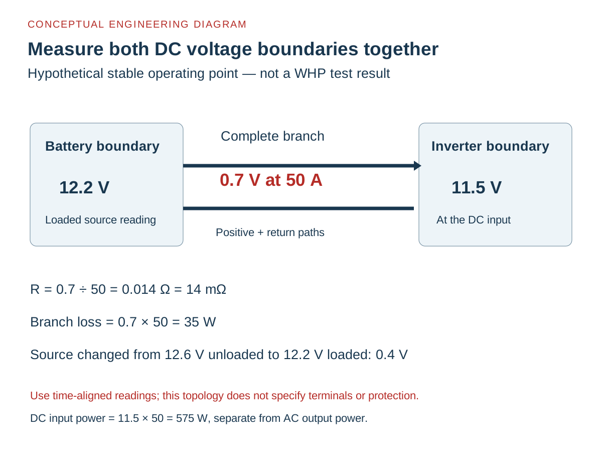
Swipe horizontally on a small screen, or open the full-size diagram.
What changes during a short load event?
A short event requires adequate time alignment and measurement response. A slow display may miss a brief minimum, while two unsynchronized readings can create a false voltage difference. Select the acquisition method from the event duration and the equipment's documented test requirements.
The steady relationship V_drop = I × R is useful for the example above. During a fast change, wiring inductance, source behavior and instrument response may also affect the observations. Do not derive a constant resistance from an unmatched pair of short-lived voltage extremes or assume that a steady calculation predicts a protection response.
For branch drop, calculate source voltage minus inverter-input voltage at the same instant. Separately recorded minimum values cannot establish that difference when the minima occurred at different times. Keep the time records so that the engineer can compare corresponding points. Note load-command timing, input-voltage behavior, current and the actual inverter indication without declaring that one event caused another solely because they happened close together.
| Observation | What it can support | What remains to check |
|---|---|---|
| Source and input fall together with a small difference | A source-side contribution is plausible | Battery state, source connections, operating conditions and actual input limits |
| Source remains higher while input falls | A contribution exists between the selected boundaries | Complete branch, contact condition and measurement alignment |
| Input minimum appears during load startup | The event deserves a time-based comparison | Current profile, acquisition response and ordered protection behavior |
| Output stops while sampled input looks normal | The available record has not established input undervoltage | Missed transients, other protection causes and instrument coverage |
How should the diagnostic record be collected?
Collect a repeatable record that identifies the unit, boundaries, instruments and event, then investigate the actual result. Do not define success as keeping the inverter running by defeating protection or using an unsupported battery setting. Equipment acceptance needs the appropriate operating limits and the complete system design.
- Identify the ordered configuration. Record the delivered inverter model and input/output options. Reconcile them with the intended source and load rather than transferring a threshold from another family member.
- Draw the measurement boundary. Mark the source and inverter sensing points, positive path and return path. Record the protective and switching components included between the points.
- Select the acquisition method. Establish suitable instruments, ranges, timing and connection arrangements for the circuit and expected event. Keep the equipment's energy-control procedure and component instructions applicable to the work.
- Record a defined baseline and event. Capture the relevant source condition, load state, both voltages and current. Record the duration and whether readings were simultaneous, averaged or captured as a time series.
- Compare within the actual coverage. Calculate steady drop and loss only where the assumptions apply. Compare an event with the ordered unit's documented limits and behavior; retain uncertainty where sampling missed the relevant interval.
- Investigate and repeat after an authorized correction. Locate the cause using the equipment procedure, record the correction and repeat the affected observations. Keep the original result rather than replacing it with only the improved reading.
An inspection finding and an electrical measurement should support each other. A tidy-looking connector is not proof of a low-resistance path, and a calculated total branch drop does not identify which joint is responsible. Keep the conclusion tied to what the recorded boundaries and instruments actually establish.
What should you send with an input-sag enquiry?
Send the full ordered configuration, source arrangement, branch schematic, sensing-point locations, load event and synchronized voltage/current record. Include the inverter's observed indications and applicable environmental conditions. State the instrument limitations so that an omitted transient is not mistaken for proof that no transient occurred.
Review the WHP-2000 ordered-option information, then send WEHO your input-event evidence. Ask for the operating and protection information applicable to the supplied unit; a nominal battery label is insufficient for that comparison.
Engineering FAQ
Does a battery monitor reading prove the voltage at the inverter?
A battery monitor reading does not establish the inverter-terminal voltage unless its sensing boundary and timing provide that measurement. Record where the monitor is connected and what it can capture. Downstream branch losses and short events require appropriate coverage.
Can I identify a bad cable from total branch resistance alone?
Total branch resistance alone cannot identify a bad cable. The estimate includes all elements between the selected boundaries, including contacts, switching components and the return path. Use the equipment's approved diagnostic procedure to locate the contribution.
Is the hypothetical 11.5 V reading an undervoltage threshold?
The hypothetical 11.5 V reading is not a WHP undervoltage threshold or an installation acceptance value. It is one calculation input. Obtain the operating limits and protection behavior for the exact ordered unit before interpreting an interruption.
Does a lower steady drop prove startup will be successful?
A lower steady drop does not by itself prove successful startup. Check the actual startup-current profile, source response, transient voltage and protection behavior with suitable acquisition. The relevant event may differ from the stable condition used in the resistance calculation.



