Key Engineering Takeaways
- Allocate each lighting branch to its approved phase pair, then verify actual line currents.
- Equal driver counts do not guarantee equal demand; include the operating states of each lighting zone.
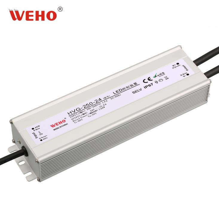
- The HVG-250 series lists 300–500 VAC input. Confirm the delivered HVG-250-24 input instructions before specifying a connection.
- Retain an allocation schedule, a measurement plan and an as-built check as separate project records.
Why Does Driver Count Not Prove Current Balance?
A lighting project can connect multiple high-line drivers to a three-phase distribution system using approved phase-pair branches. A schedule showing the same number of drivers on each pair may be a useful starting point, but it does not establish the actual line currents during all lighting states. Different branches can carry different loads, and electronic input currents may not have identical waveforms or phase relationships.
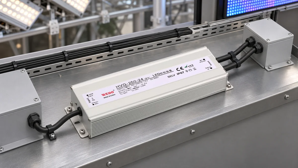
IL HVG-250-24 high-line driver provides the product context for a planning record. The family page lists 300–500 VAC input. A qualified designer must verify the delivered unit's applicable input, protective-earth and installation requirements as well as the actual supply system; this article is not a field wiring procedure or an approval of a particular phase-pair connection.
What Is Being Allocated in a Three-Phase Project?
The upstream supply system and the individual driver's input are different things. A project drawing may identify three supply lines as A, B and C, while an individual driver receives AC through the input conductors specified for that unit. A protective-earth connection, where required, serves a different function and must not be omitted from the design or treated as one of the load-current phase allocations.
Before assigning branches, the responsible designer should establish the actual distribution topology, relevant conductor and earth arrangements, input voltage under the required conditions, and the manufacturer's applicable connection instructions. Do not infer a neutral conductor, a grounded conductor or a particular protective-device arrangement merely from the words “three-phase.”
After the available AC feed has been identified, the next task is documenting how multiple candidate branches are allocated and how a project will verify the resulting line currents. A product-family input range does not authorize an arbitrary site connection or prove that the complete lighting system is suitable.
How Should a Phase-Pair Schedule Be Read?
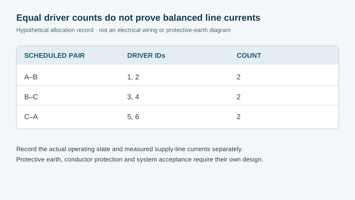
Consider a hypothetical project with six drivers of the same nominal model. A designer's preliminary schedule assigns two to pair A–B, two to B–C and two to C–A. The schedule describes equipment allocation only. No installation, actual wiring, measured balance or certification is represented.
| Hypothetical pair | Scheduled driver IDs | Quantity | What remains to verify |
|---|---|---|---|
| A–B | Driver 1, Driver 2 | 2 | Actual circuit and operating-state currents |
| B–C | Driver 3, Driver 4 | 2 | Actual circuit and operating-state currents |
| C–A | Driver 5, Driver 6 | 2 | Actual circuit and operating-state currents |
| Three supply lines | All six scheduled drivers | 6 | Measured line currents and project acceptance criteria |
Two drivers assigned to a pair do not necessarily draw the same input current as two assigned elsewhere. Their operating states, actual connected loads, supply voltages and unit tolerances can differ. If one zone is switched off while another remains on, the equal installation count no longer describes equal active demand.
Line current also depends on how branch currents combine in time. Do not add two RMS magnitudes as ordinary numbers or divide total lighting wattage by three and call the result a measured line current. Real electronic loads can have non-sinusoidal current, so an assessment must use an appropriate method and measurement bandwidth for the system rather than a single assumed power factor.
Schneider Electric discusses harmonic currents in a three-phase system using phase-to-neutral loads in the context of its equipment. That example illustrates why waveform content can matter; it is not an HVG-250-24 test or a calculation for the phase-pair schedule above.
Which Operating States Should the Record Cover?
Agree on the states that matter to the equipment before commissioning. They might include all intended lighting zones on, one selected zone off, the minimum normal operating state and other combinations defined by the project. Do not assume that a particular HVG-250-24 variant supports dimming or another control feature without the applicable documentation.
For each state, record which branches and loads are active, the time and the measurement points. The record should distinguish individual driver-branch quantities from the currents on the three upstream supply lines. Other equipment sharing the feeder must be accounted for or explicitly excluded; otherwise a line-current reading cannot be attributed solely to the lighting drivers.
Voltage and current observations should describe the same state and a suitable common time interval. Sequential readings may be useful for stable conditions if the method and its limitations are documented. Where changing loads or waveform relationships matter, the project engineer should specify appropriate synchronized measurement equipment and analysis.
What Should Procurement and Engineering Retain?
| Il record | Procurement use | Engineering use |
|---|---|---|
| Full model and revision | Match the ordered HVG-250-24 and supplied documents | Identify the unit and applicable input requirements |
| Input evidence | Retain the current manufacturer specification | Compare actual system conditions with applicable limits |
| Branch allocation | Associate quantities and IDs with the project schedule | Trace each planned or as-built phase-pair assignment |
| Operating-state record | Identify the intended project duty | Interpret each measured branch and line current |
| Acceptance and changes | Track the approved document set | Record criteria, results and subsequent configuration changes |
The design record should separately address conductor protection, disconnecting means and fault isolation according to the actual system, equipment instructions and applicable local rules. Those choices are not determined by the number of drivers or by a generic table in a blog. The designer should also determine the required measurements, operating conditions and acceptable imbalance criteria for the project.
How Should the Project Verify the Schedule?
- Identify the supplied drivers. Record the full model, revision, input details and applicable installation documents. Confirm any differences between the order, label and manufacturer documentation before use.
- Establish the system topology. Have the responsible electrical designer document the real supply, conductor and protective-earth arrangement and confirm each intended branch is suitable.
- Prepare the allocation record. Map each driver or branch ID to its approved phase pair and lighting zone. Keep the design schedule distinct from a verified as-built record.
- Define the measurement plan. Specify the operating states, measurement boundaries, relevant feeder loads, instruments and project acceptance criteria. Identify whether synchronized waveform or harmonic data is needed.
- Measure under authorized procedures. Qualified personnel should follow the site's electrical-safety and energy-control procedures and use appropriately rated equipment. This article does not provide instructions for connecting test instruments to an energized high-voltage circuit.
- Compare and control changes. Record the actual conditions and measured result. Investigate discrepancies, update the as-built schedule and repeat affected checks after relevant changes to branches, loads or controls.
Do not treat a hypothetical balanced count, a product-page input range or a single set of meter readings as complete protection or compliance approval. Acceptance requires the responsible designer's assessment of the actual equipment and applicable requirements.
Request HVG-250-24 Input Information
For an HVG-250-24 project review, provide WEHO with the full model and revision, intended supply conditions, number of drivers, actual lighting load and the relevant project questions. Ask for the applicable input, installation and protective-earth documentation. Provide the branch schedule to the responsible electrical designer for the system-level review.
Engineering FAQ
Is the HVG-250-24 itself a three-phase supply?
The project can use a three-phase distribution system while individual drivers use their specified AC input conductors. Confirm the exact unit's input and protective-earth instructions; do not infer a three-phase product input from the upstream project.
Do two drivers on each phase pair guarantee balanced line currents?
No. The count is an allocation, not a measurement. Operating states, input conditions and current waveforms can differ and must be assessed under the project's defined conditions.
Can I calculate a line current by adding two RMS branch readings?
Not generally. Branch currents combine with their time and phase relationships, and non-sinusoidal components can matter. Use an appropriate engineering method and measurements for the actual system.
Does the 300–500 VAC series listing specify the project breaker?
No. The input range does not determine the entire conductor-protection and isolation design. The responsible designer must use the actual equipment, circuit and applicable requirements.
Does a phase-pair schedule replace an as-built check?
No. A schedule states an intended allocation. The project must establish whether the actual installation matches the approved design and retain the relevant verification record.