A fan-cooled industrial power supply needs a defined route for cooling air and a practical maintenance plan inside the finished enclosure. A visible fan is not evidence that the cabinet can remove the heat. Review the inlet, outlet, nearby obstructions and service access before approving the mechanical layout.
On this page
This guide helps an OEM release the cooling arrangement of a fan-cooled supply. Its output is an installed airflow and service record, rather than a universal clearance dimension or an assumed fan-replacement interval.
Identify the complete cooling assembly
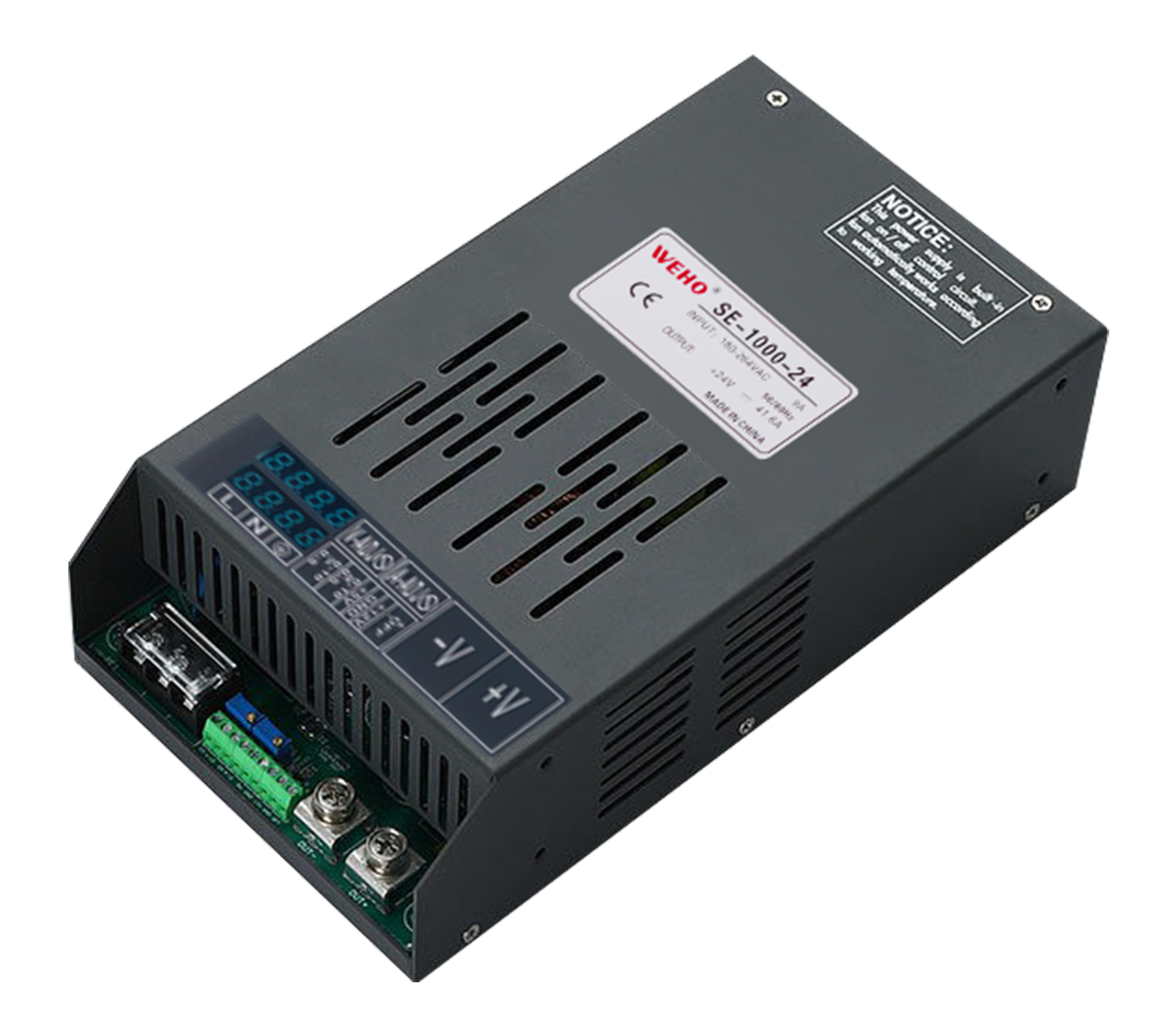
IL WEHO SE-1000-24 industrial power supply is the identified variant for this cooling review. The SE-1000 family page describes an internal speed-controlled fan; confirm the ordered variant and applicable installation instructions. The fan behavior, minimum clearance and allowable inlet conditions belong to that assembly; do not transfer them from a similar enclosure.
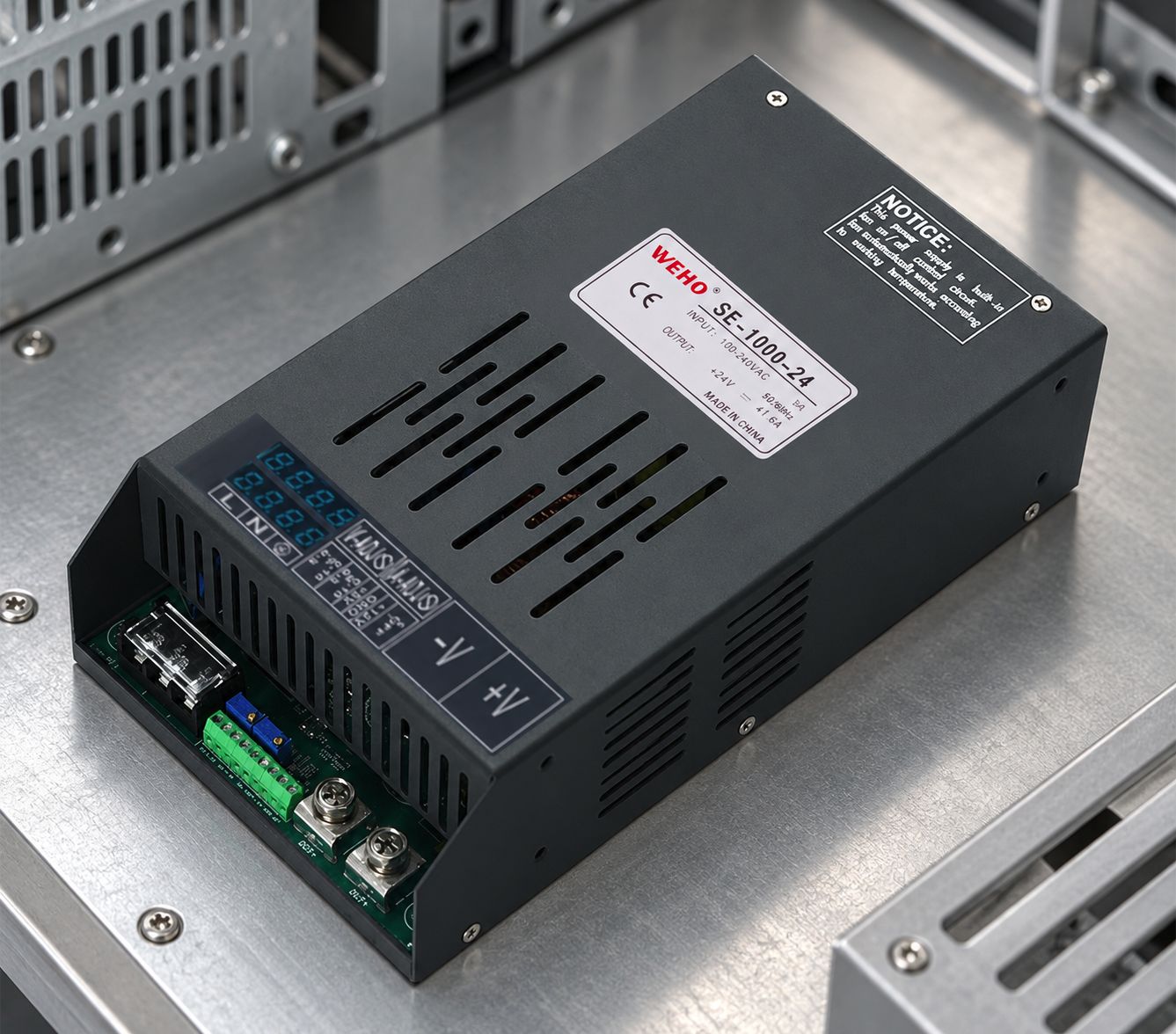
Keep three roles distinct: the supply’s own cooling system, a cabinet ventilation system and the room or process environment. A supply fan can move air through its case without providing enough air exchange for the whole cabinet. Likewise, a cabinet fan nameplate gives a component rating, not the measured airflow through the installed restrictions.
Map the inlet, outlet and nearby heat
Start with the manufacturer’s airflow direction and permitted mounting orientation. Mark where air enters the supply and where it leaves. Identify cable ducts, mounting plates, adjacent supplies and door-mounted equipment that may restrict that route or return warm exhaust to the inlet. Do not assign inlet and outlet directions from a photograph alone.
Record the local supply-inlet temperature as well as the broader enclosure condition. A room sensor can miss a warm pocket near a cabinet wall or above another heat source. If the installation changes, retain comparable measurement locations so the review answers the same question.
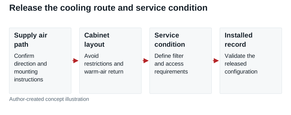
| Layout item | What to record | Release question |
|---|---|---|
| Supply air path | Manufacturer direction and allowed surrounding space | Does the released layout preserve it? |
| Cabinet exchange | Ventilation arrangement, restrictions and local inlet conditions | Where does rejected heat go? |
| Filters and guards | Exact fitted parts and access method | Can the agreed service task be completed? |
| Adjacent equipment | Heat sources and simultaneous operating states | Does their operation change the supply inlet? |
Separate heat estimation from airflow qualification
For a calculation example, assume a supply delivers 600 W at a measured 90% efficiency under the stated condition. Its input real power is 600 ÷ 0.90 = 666.7 W, leaving approximately 66.7 W to be rejected. At 85% efficiency, the corresponding loss would be about 105.9 W. These assumed cases show why the operating point matters; they are not SE-1000-24 efficiency measurements.
A heat estimate is useful for comparing layout options, but it does not establish the required airflow, a fan operating point or component temperatures. Avoid adding the free-air CFM ratings of several fans and calling the result installed ventilation. Obtain the applicable cooling requirements and verify the assembled equipment with its actual restrictions.
TDK-Lambda’s explanation of supply cooling and audible noise discusses the interaction of airflow, obstructions, fan operation and heat loss. Its product examples do not establish WEHO clearances, fan-control behavior or noise performance.
Define a realistic service condition
Specify how the external filter or ventilation guard is inspected, how access is obtained and what evidence triggers service. Any interval should follow the equipment’s environment, manufacturer instructions and observed condition. A clean office and a dusty production area should not share an invented universal cleaning schedule.
Where the design relies on a filter, qualification should include its agreed service condition rather than only a new, unrestricted element. Define that condition with the responsible engineering team. Do not intentionally block a supply fan or perform an internal modification as an improvised test.
State whether the service task concerns external cabinet parts or the supply itself. An accessible fan grille does not mean its internal fan is user-replaceable. If a fan fault requires replacing the complete supply, leave the removal path, approved isolation procedure and replacement configuration in the equipment service plan.
Qualify the finished layout
Use the released enclosure, cabling, filters and neighboring equipment for the acceptance run. Record input, load, ambient conditions, local inlet temperature, operating duration and permitted temperature observation points. Include the equipment’s relevant simultaneous states and the agreed service condition. Do not infer thermal margin from sound level or the fact that a fan is spinning.
Retain the layout drawing and cooling-component identities with the test record. A new filter material, relocated duct or different neighboring assembly can change the installed condition even when the power-supply model remains the same.
Send WEHO your enclosure cooling and service requirements with the intended SE-1000-24 configuration, load, inlet environment, layout and maintenance constraints. Request the applicable mounting and cooling instructions before approving the cabinet.