



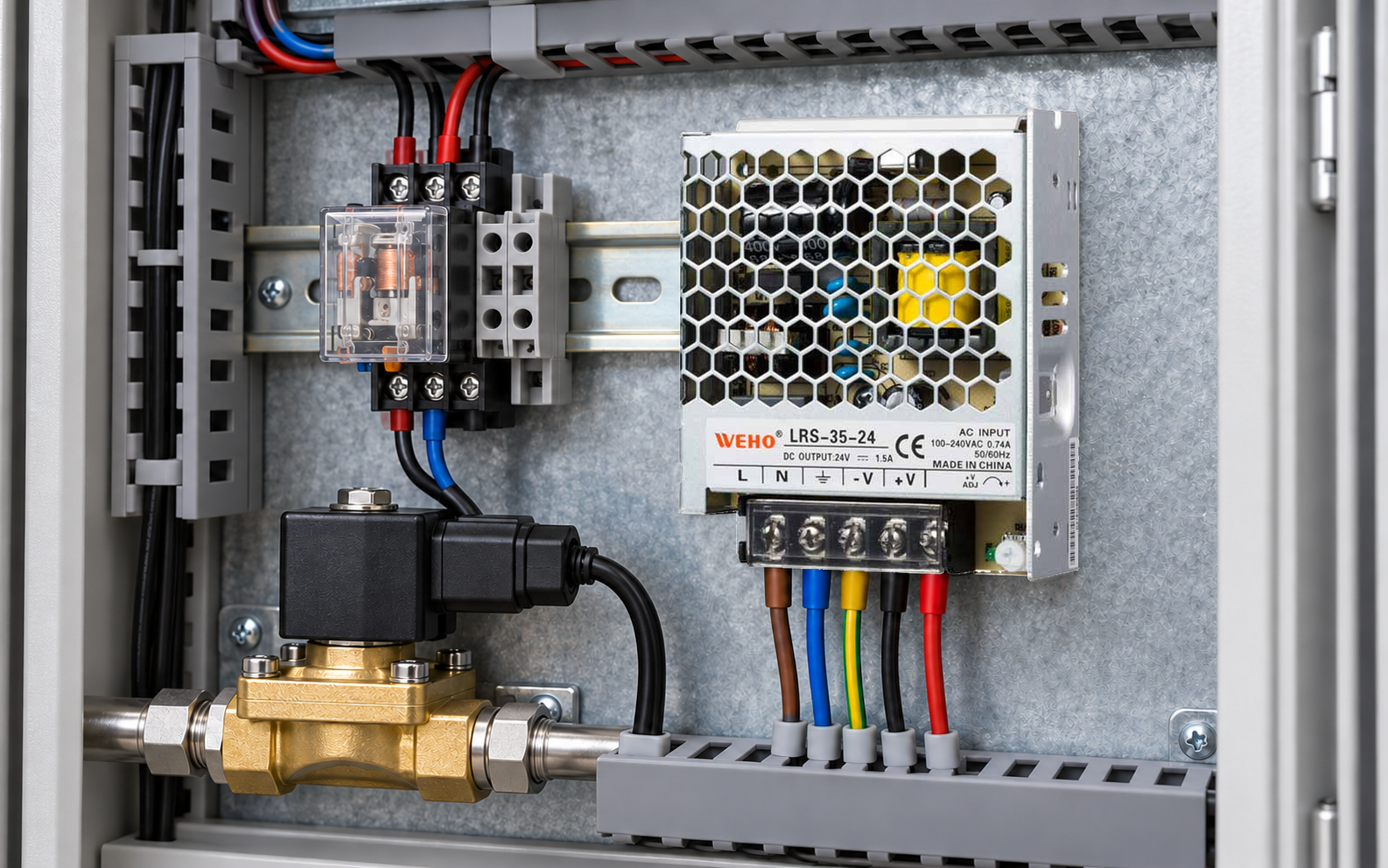
Qualify solenoid turn-off with two results: how the coil current decays and when the required mechanical response occurs. An acceptable 24 V supply reading does not establish either result. If a replacement connector adds a suppression diode and a valve begins releasing later, investigate the complete coil-driver-suppressor combination before assuming the power supply needs more watts.
This guide is for an OEM reviewing a non-latching DC solenoid branch. LRS-35-24 provides the product reference; no particular valve, suppression component or controller is claimed compatible. The deliverable is a controlled comparison and release record, with acceptance limits taken from the actual equipment requirements.
Keep the supply decision separate from the turn-off decision
IL WEHO LRS-35 product table E official specification sheet identify LRS-35-24 as a nominal 24 V version with a listed 0–1.5 A output range. Those figures identify a candidate source for a documented branch budget. They do not specify a valve’s release time, an external switch’s clamp capability or the supply’s ability to absorb returned energy.
Complete the ordinary simultaneous-load and installation review separately. This article asks a narrower question: after the electrical OFF command, does the intended mechanism reach its required state within its approved conditions? A larger source rating is not evidence that a changed suppressor will meet that requirement.
Use one command event and two response observations
Define the time origin at the actual command reaching the output stage, rather than an earlier PLC instruction or a screen indication. Then record an electrical response and an independently observed functional response. Agree the definitions before comparing candidates.
| Event | Definition to put in the test plan | What it cannot establish alone |
|---|---|---|
| t0: OFF command | The actual driver-control transition and its measurement point. | That coil current stopped immediately. |
| tI: current condition | A documented coil-current threshold, direction and persistence rule. | That the valve or mechanism reached its required position. |
| tM: functional response | The agreed position, contact or process-feedback event. | That switching voltage and energy stayed within component limits. |
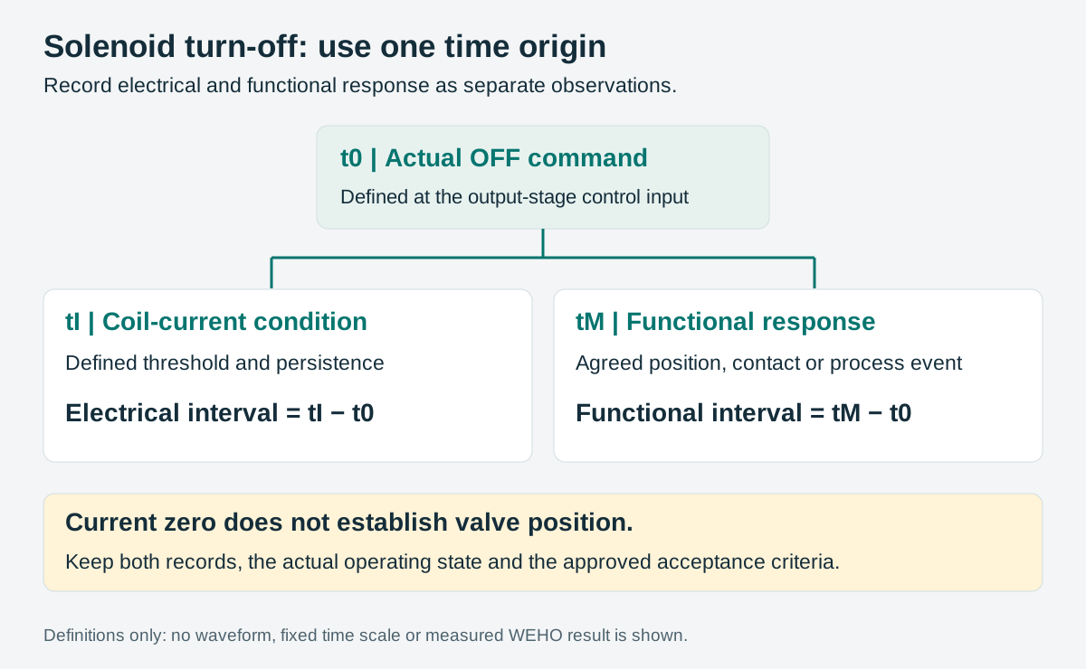
Report tI − t0 and tM − t0 from the same capture or a synchronized record. Do not automatically label the current-zero point “valve released.” Pressure or flow feedback can include downstream process delay; if used, name that event honestly rather than presenting it as direct armature-position evidence.
Understand the tradeoff without selecting an arbitrary clamp
Texas Instruments’ SLVAE59A explains that freewheeling and clamping produce different coil-current decay behavior. A diode provides a recirculation path; a higher opposing clamp voltage can reduce electrical decay time. Its examples distinguish that electrical interval from the solenoid’s total de-actuation time. Their measured values belong to TI’s example circuit, not to an LRS-35-24 installation.
The choice also affects where energy is dissipated and the repeated-switching duty. TI’s inductive-load application brief connects discharge energy, heat and switching frequency. Faster decay therefore needs a documented driver, suppressor and load review. It is not permission to increase a clamp voltage until motion looks fast enough.
Check for a diode, LED network or electronic drive already inside the valve connector or coil assembly. Adding another parallel path can change the intended behavior. Use the actual assembly documentation; this guide supplies no universal diode, TVS voltage or switching-voltage allowance.
Compare approved candidates under a controlled condition set
Use the equipment designer’s controlled procedure and suitable instrumentation. The comparison must not create uncontrolled movement or require removing suppression as an improvised baseline. Compare only configurations that the responsible component and equipment reviewers permit.
| Keep or record | Why it belongs in the comparison |
|---|---|
| Exact coil, driver, connector and suppressor revisions | A changed plug can contain a different circuit despite a similar exterior. |
| Supply setting and voltage at the relevant points | Separate a source/bus change from a suppression change. |
| Initial coil current and energization history | Different starting conditions can change the observed decay. |
| Coil temperature and mechanical/process conditions | Do not compare a cold baseline with a warm candidate without identifying the difference. |
| Voltage reference, sensing method and trigger | Keep current, switch voltage and feedback traces interpretable together. |
| Required interval, repeat duty and acceptance source | A single quick event cannot establish the full production duty. |
TE Connectivity’s coil-drive guidance shows why coil resistance, temperature and drive conditions affect electromechanical behavior. Its relay examples are background for controlling conditions, not a valve specification or a substitute for the selected coil’s limits.
Use the observations to choose the next investigation
| Observed pattern | Next question |
|---|---|
| Command reaches the driver late; responses follow it | Is the delay in control logic or the output stage rather than the coil? |
| Current decays slowly and functional response is late | Does the documented suppression path explain the electrical interval? |
| Current condition is reached promptly but functional response is late | What do the valve, mechanism and process-feedback records show? |
| Functional timing is acceptable but voltage or thermal limits fail | Can the complete candidate be released under the required repeated duty? |
These patterns guide investigation; they do not establish a cause from one trace. Keep raw records and note any concurrent change. If the bus voltage rises during turn-off, identify the energy path and relevant limits rather than assuming the switching supply can sink that energy.
Release the combination and its change triggers
The release file should name the coil, driver, connector and suppressor parts, accepted operating conditions, event definitions and record references. Retain both electrical and functional results, including exceptions and the person responsible for closing them.
Reopen the check after a connector substitution, an added suppression component, a driver revision or a changed switching sequence. Preserve the approved branch budget and the LRS-35-24 source revision alongside the timing evidence. This is a coil turn-off review; relay contact breaking ratings and safety-function validation remain separate engineering tasks.
Use the project record
Open the blank Solenoid turn-off comparison and release record to record your conditions, evidence and decisions. The worksheet contains no pre-approved result.
For an LRS-35-24 enquiry, provide the actual branch budget and supply conditions. Take the coil, driver and suppressor documentation to the equipment reviewer when release timing is part of the requirement.




