



- Select a PPTC from its applicable hot-ambient hold-current data, voltage and fault conditions.
- A tripped PPTC limits current through high resistance; it does not provide an open isolation gap.
- Removing a fault does not guarantee immediate reset while the device remains heated or energized.
- Qualify the complete branch and restart sequence separately from the power supply’s own protection.
Why a resettable branch can remain off after the fault clears
A small machine branch recovers on a cool bench but remains unavailable inside a warm cabinet after a fault is removed. Increasing the power-supply current rating may not resolve the problem. The branch's polymeric positive temperature coefficient device, or PPTC, may have less hold-current capability at its local temperature and may remain in a heated high-resistance state.
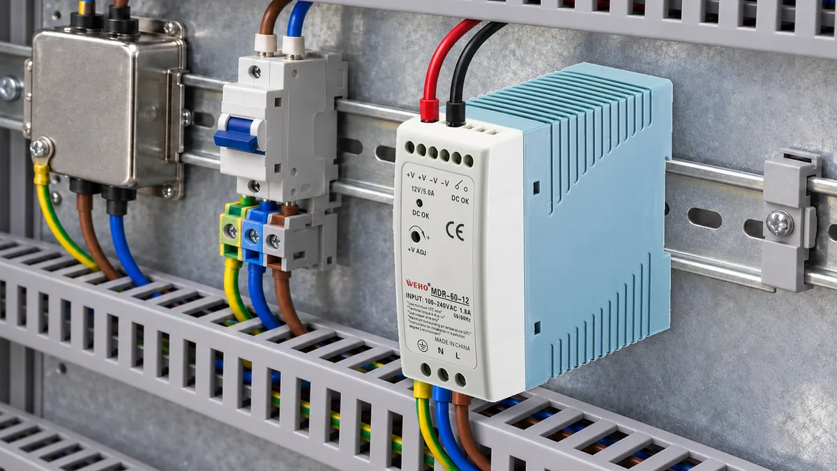
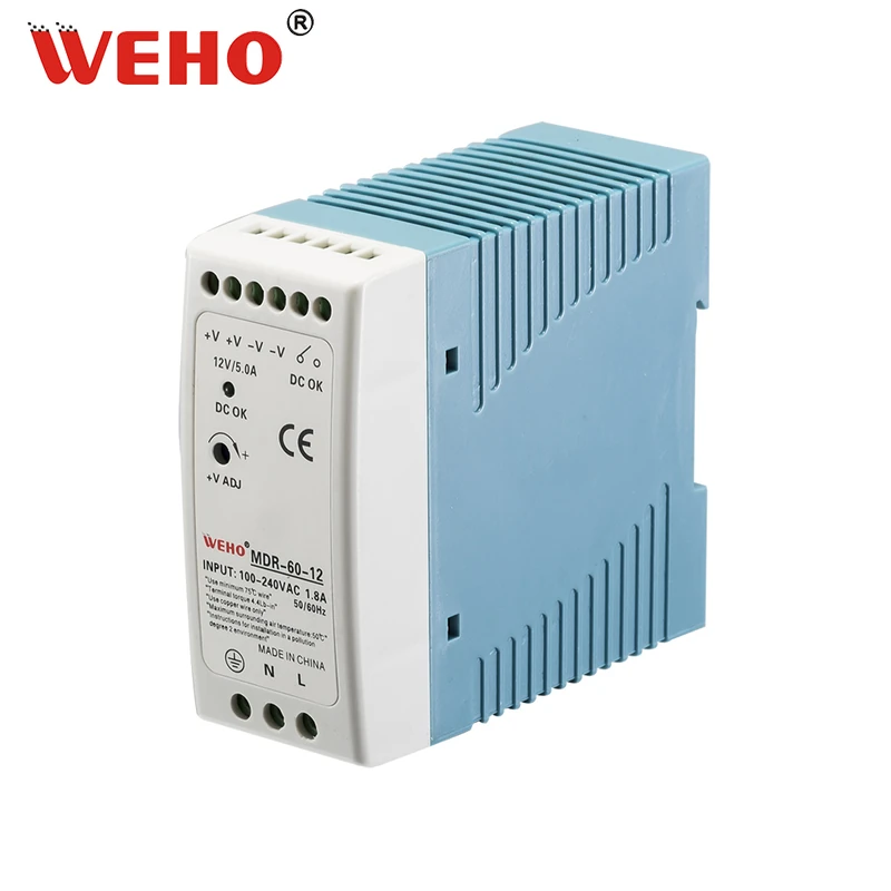
IL WEHO MDR-60-12 product reference provides a 12 V supply context for the engineering review. This article evaluates an externally designed branch protection arrangement. It does not claim that MDR-60-12 contains the illustrative PPTC, specifies its reset behavior or guarantees coordination with a selected component.
Understand what a tripped PPTC actually does
A PPTC responds to thermal conditions by increasing resistance and limiting circuit current. Littelfuse's resettable-functionality technical paper distinguishes that behavior from a fuse that interrupts current. A tripped branch can retain voltage and leakage current, so its state must not be treated as safe electrical isolation.
Hold current and trip current are conditional ratings rather than a single precise switching threshold. The region between them does not establish an acceptable continuous operating point for every installation. Trip time, ambient temperature, thermal coupling, previous operation and the particular device data all matter to the branch decision.
For example, the Littelfuse 1206L datasheet defines its hold and trip ratings at 20°C in still air and supplies temperature-specific data. Those conditions belong to that component family. Do not substitute cabinet room temperature for the local thermal conditions of a different selected PPTC.
Check the maximum applied voltage and prospective fault conditions as separate requirements. A part's hold-current number does not establish its voltage capability or ability to withstand the available fault current. The upstream source, connected capacitance and any other energy source must be included in the protection review.
Calculate hot-ambient hold-current reserve
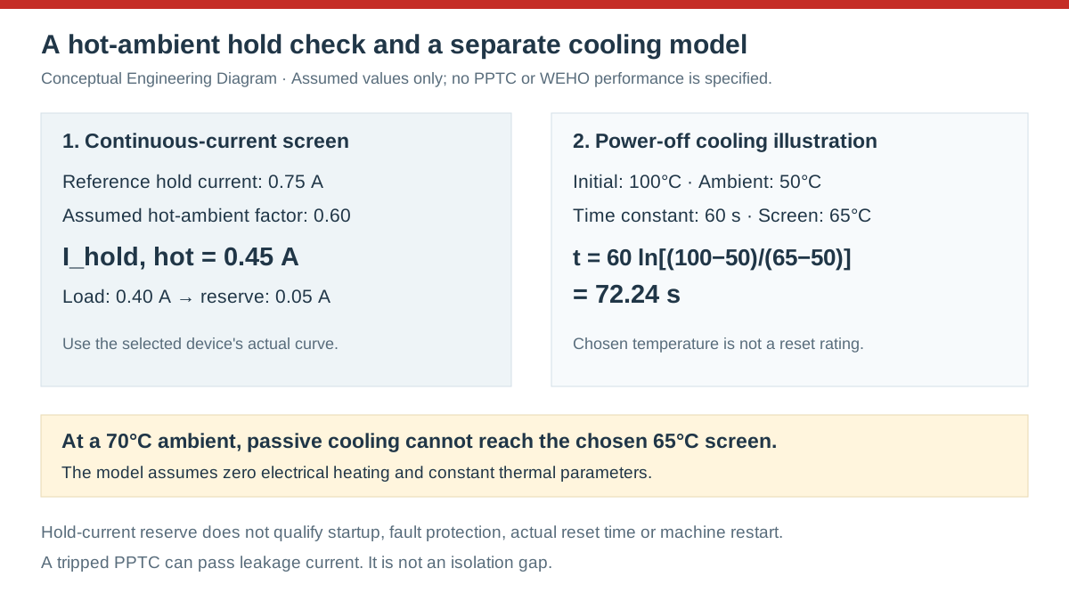
Assume a hypothetical PPTC has a 0.75 A hold-current rating at its stated reference temperature. For this example only, assume its applicable curve gives a factor of 0.60 at a local 60°C ambient. The screened hot hold current is 0.75 × 0.60 = 0.45 A; the factor is not a WEHO rule or data for a particular marketed PPTC.
If the branch requires a maximum continuous 0.40 A, the arithmetic reserve is 0.45 − 0.40 = 0.05 A. That is only 12.5% of the assumed load current. If a higher-temperature condition instead produces a hypothetical factor of 0.45, the available hold current becomes 0.3375 A and the same load no longer passes this screen.
| Hypothetical condition | Applied hold-current factor | Screened hold current | Decision for 0.40 A continuous load |
|---|---|---|---|
| Reference condition | 1.00 | 0.7500 A | Continuous-current screen passes |
| Chosen 60°C case | 0.60 | 0.4500 A | Only 0.0500 A reserve remains |
| Chosen hotter case | 0.45 | 0.3375 A | Continuous-current screen fails |
This comparison does not establish startup acceptance or a guaranteed trip time. Review the actual time-current information for the load's startup pulse and the selected device's initial thermal state. A repeated start before full cooling can create a different condition from the first start after a long power-off period.
Measure the environment at the component's actual location in the intended assembly. Nearby resistors, converters, duct routing, PCB copper and airflow can change its thermal behavior. A cabinet ambient measurement remains useful context, but it cannot by itself establish the selected component's condition under all branch loads.
Separate fault removal from thermal reset
A reset decision needs the fault cleared and the device able to cool into the required resistance state. In some circuits, continuing dissipation sustains the high-resistance condition after the original fault is removed. The component instructions and complete circuit determine whether removing input power, reducing voltage or another approved action is required.
Consider an illustrative instantaneous check with 12 V across an assumed 120 Ω hot device. Current is 12 ÷ 120 = 0.10 A, and dissipation is 12² ÷ 120 = 1.20 W. This shows why a limited current is not the same as zero heating; it is not a prediction of a PPTC's hot resistance or steady-state temperature.
Reset time also depends on the cooling environment. For an explicitly simplified power-off model, assume an initial device temperature of 100°C, local ambient of 50°C and a thermal time constant of 60 seconds. Choose 65°C as an illustrative reset-screen temperature, not a published switching temperature of an actual component.
The lumped cooling model is T(t) = T_ambient + (T_initial − T_ambient) × e^(−t/τ). Solving for the chosen threshold gives t = 60 × ln[(100 − 50) ÷ (65 − 50)] = 72.24 seconds. This result assumes zero electrical heating, constant ambient and constant model parameters.
If ambient is 70°C, passive cooling toward 70°C cannot reach the chosen 65°C threshold in this model. A fixed “wait one minute” instruction would therefore fail even before circuit details are considered. Real reset qualification must use actual resistance recovery and component instructions rather than treating this simplified temperature model as a service timer.
Swipe horizontally on a small screen, or open the full-size diagram.
Check the branch together with the upstream supply
Review source behavior during the branch fault without assuming a larger current rating improves protection. Source current limiting or intermittent recovery can change the heating applied to the PPTC, while another branch may share the same supply. The design must preserve the intended protected conductors and required behavior of unaffected loads.
Bourns provides a Multifuse product-selection worksheet for collecting application conditions and reviewing device selection. Use the actual selected device's conditions and data rather than choosing by footprint and room-temperature current alone. Record any unresolved coordination question before the branch design is released.
Define what the equipment should do after a successful electrical reset. Automatic restoration may be acceptable for one monitoring branch and unsuitable for a machine action that requires a deliberate restart. A PPTC's thermal recovery does not establish the controller's restart logic or a safety-rated stop function.
Keep the separate ownership record described in WEHO's equipment restart review alongside the branch test. That review addresses component, control and restart permission; the present calculations address the external PPTC's ambient and recovery conditions.
Qualify hold, trip and recovery as separate cases
- Identify the protection task. Record the conductor, load, operating voltage, available fault energy and required behavior. Accept the definition when the branch diagram shows every relevant source and the intended protected boundary.
- Check continuous operation. Apply the selected component's hold-current data to the local thermal conditions and maximum continuous load. Record the curve or table revision; accept only the operating cases supported by the design rule.
- Check startup and faults. Compare required startup with applicable device data, then evaluate the defined fault cases using an approved test plan. Save current, voltage and timing records; accept the cases only against the stated protection requirements.
- Verify reset conditions. Clear the fault and apply the documented power-removal or voltage-reduction method. Record ambient, off time, recovered resistance and restart result; accept when the branch reliably returns to its required state under the defined conditions.
- Control the restart. Verify the receiving equipment's behavior after the branch returns. Record whether a new command is required, and release the assembly only when the required functional restart is demonstrated separately from PPTC recovery.
Keep the first cold start, repeated hot starts and post-fault restart as distinct records. A successful first operation does not qualify the thermally stressed cases. A different enclosure, PCB or nearby heat source can require review even when the PPTC part number and nominal load remain unchanged.
Prepare an MDR-60-12 branch-protection enquiry
Send WEHO the MDR-60-12 candidate reference, branch schematic, load states, selected PPTC data and local thermal conditions. Ask for applicable supply behavior under the stated load and fault cases without assuming component coordination. Use the Pagina contatti WEHO to provide the required recovery and restart sequence with the enquiry.
Frequently asked questions
Does a tripped PPTC completely disconnect the branch?
No, a PPTC normally limits current by entering a high-resistance state. Treat remaining voltage and leakage according to the complete circuit, and use the required isolation method for work on the assembly.
Can I choose a PPTC from room-temperature hold current alone?
No, the applicable local temperature and mounting conditions can change the hold-current screen. Voltage, fault capability, startup and reset conditions also require review.
Will removing the short circuit always reset the PPTC immediately?
No, continuing power dissipation or a hot environment can prevent or delay recovery. Follow the selected component's reset conditions and verify the actual branch recovery sequence.
Does a power supply's overload protection replace branch qualification?
No, source protection and branch protection address different boundaries. Verify the selected device, conductor, load and source behavior together under the project's defined cases.



