Direct answer: A sensor output during power-up or power-down may not represent a valid target event. Identify the exact sensor’s readiness time and documented behavior during supply transitions, then verify how the receiver handles those intervals. The correct sequence depends on the sensor, PLC or relay, load power and machine hazard analysis; a generic delay is not a safety function.
Why does a valid-looking signal appear at startup?
Electronic circuits need time to initialize after their supply rises. A receiving input can become active before the sensor has reached its documented operating condition. Conversely, a falling sensor supply can create an output change while the receiver or actuator is still powered. Omron’s proximity-sensor precautions discuss readiness and possible power-off pulses for its covered products. Its stated times and supply sequencing do not establish LJA performance.
This event differs from normal process-pulse capture. A fast counter can record an unwanted transition very reliably; filtering that suppresses an unwanted pulse may also reject legitimate events. Both electrical behavior and the receiving logic must be understood.
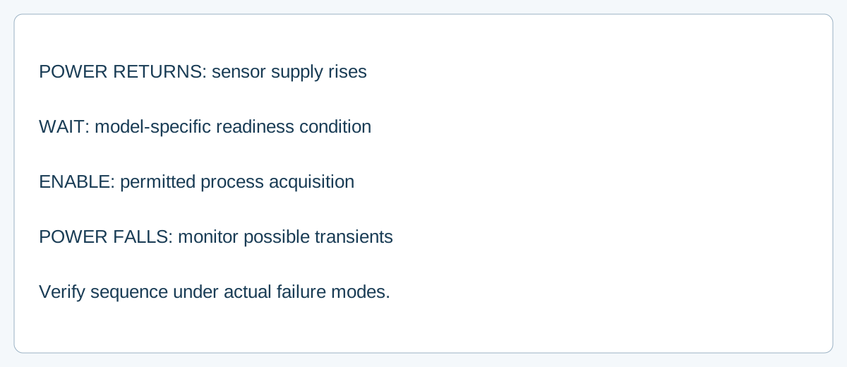
Build an event matrix before changing logic
| Event | Conditions to record | Question for acceptance |
|---|---|---|
| Power-up | Sensor and receiver supply rise, target present/absent | When is the sensor output valid and the receiver ready? |
| Power interruption | Duration, minimum voltage, downstream state | Does the system restart or retain a prior count? |
| Sensor supply falls | Receiver still energized, target state | Can an output transition be interpreted as an event? |
| Unequal supply timing | Independent sensor, input and actuator supply paths | Does every allowed sequence produce an acceptable state? |
Authorized personnel should perform supply-transition checks under the equipment’s approved controlled procedure, with machine motion and unintended actuator operation prevented as required by the test plan. Document actual waveforms and time references using suitable equipment. Specify the observation point: sensor output, receiver terminal, PLC input image and program counter may not change at the same instant.
Plan a controlled evaluation
- Obtain the complete sensor code and the manufacturer’s supply range, rise-time, startup readiness and shutdown behavior. Obtain the matching receiver’s thresholds and startup sequence.
- Identify separate power domains and what the machine should do when the sensor is not yet valid. Include power interruptions and slow voltage changes where relevant.
- Test the actual sensor with the target present and absent, in the real mechanical arrangement. Capture supply and output simultaneously through normal and abnormal transitions permitted by the test plan.
- Compare receiver and program behavior. An approved readiness signal, interlock, startup state or inhibit interval may be appropriate if supported by the design; do not invent a fixed delay from a competitor’s example.
- Repeat after changing sensor, supply, controller, load or wiring. Keep the acceptance record with hardware versions and the measured conditions.
For series-connected sensors, Omron’s FAQ describes error pulses in its two-wire examples when individual sensors do not receive rated voltage and current. Its separate three-wire example discusses a power-on pulse when one sensor supplies another. These are model-specific circuit examples; neither establishes a WEHO pulse duration or approves a WEHO circuit.
Identify the WEHO sensor correctly
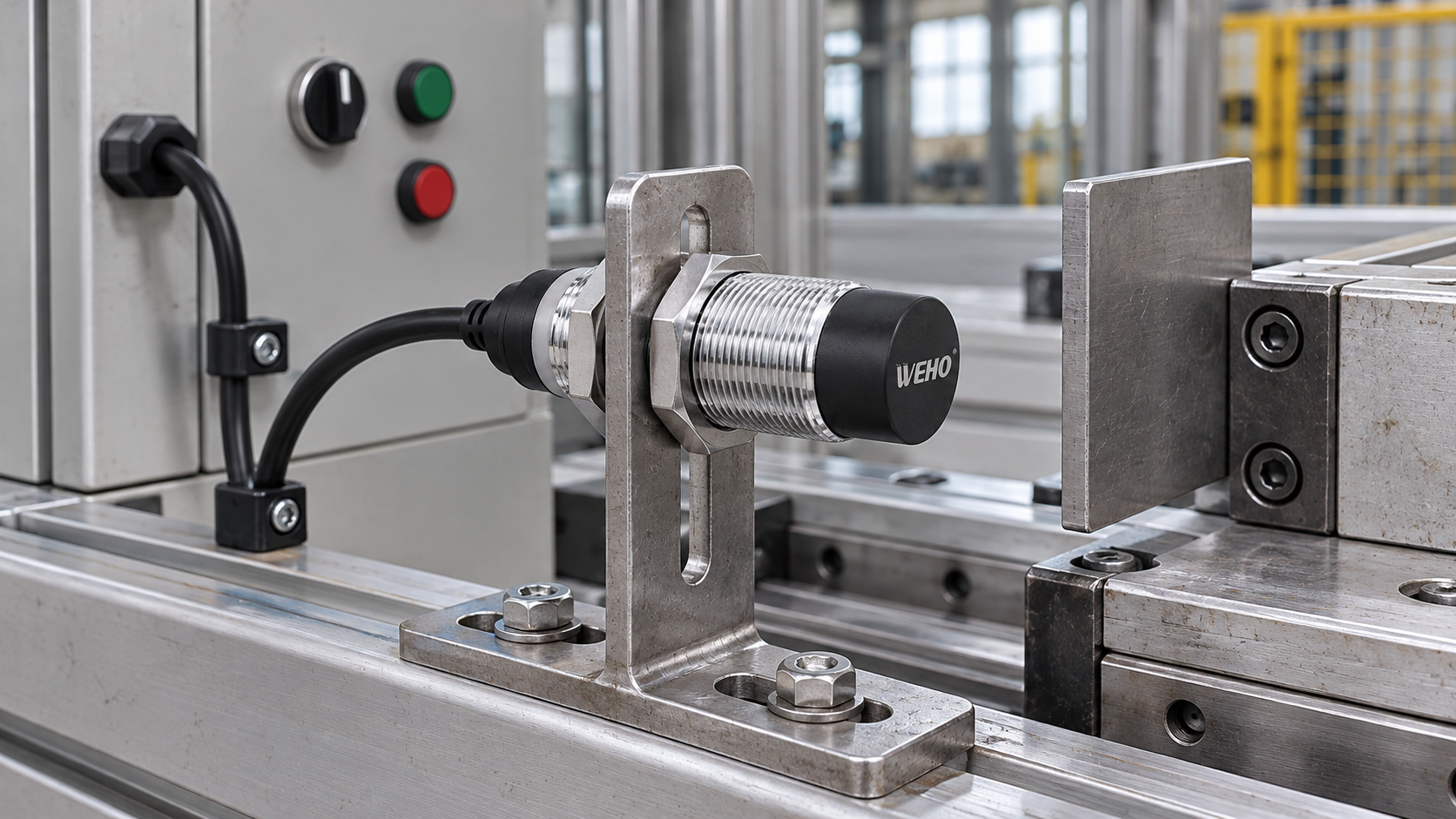
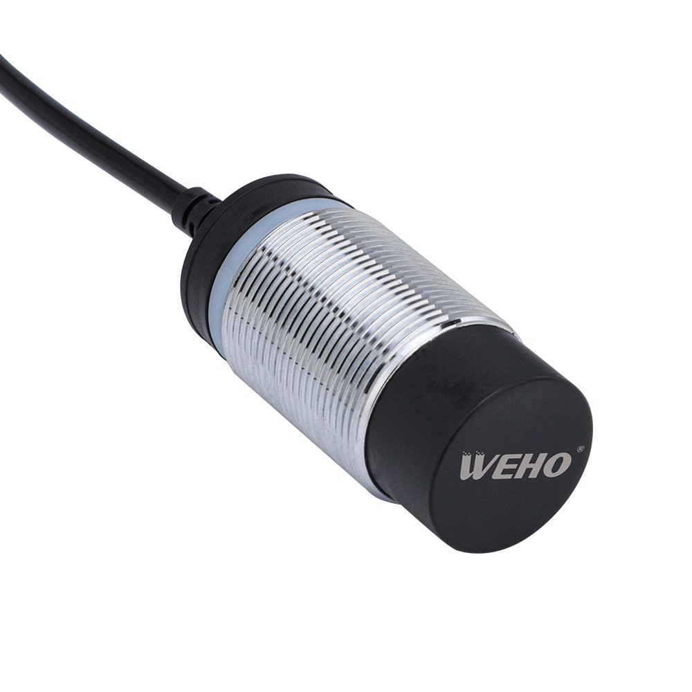
IL WEHO LJA18 product page identifies the pictured product family. Its photo does not establish a particular order suffix or its startup/shutdown limits. Ask for the controlled documentation and use the actual connected receiver’s instructions too.
Frequently asked questions
Is a delay copied from another sensor enough?
No. Readiness may depend on the actual device and supply conditions; the receiver and process must be validated with that arrangement.
Does ignoring an input during startup provide machinery safety?
Not by itself. Protective functions and their validation belong to the machine’s specified safety design.
Give WEHO the exact sensor variant, supply ramp, receiver type, intended power sequence and observed output trace. Request model-specific behavior and review the complete system with the machine designer. Contatta WEHO.