



Sensor Supply Ripple: What to Verify Before an OEM Supply Substitution
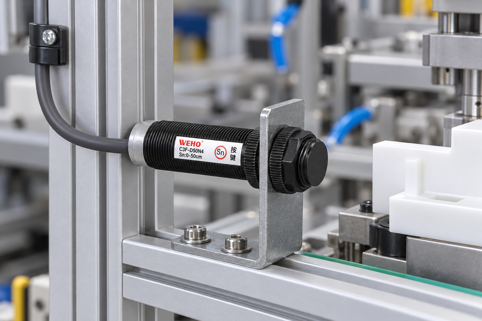
A switching power supply can be an appropriate source for an industrial sensor, but a voltage label alone does not prove a clean or compatible installation. For OEM procurement, separate three questions: whether the DC operating range is correct, what ripple and transient limits apply to the exact sensor, and what reaches the sensor terminals in the finished machine.
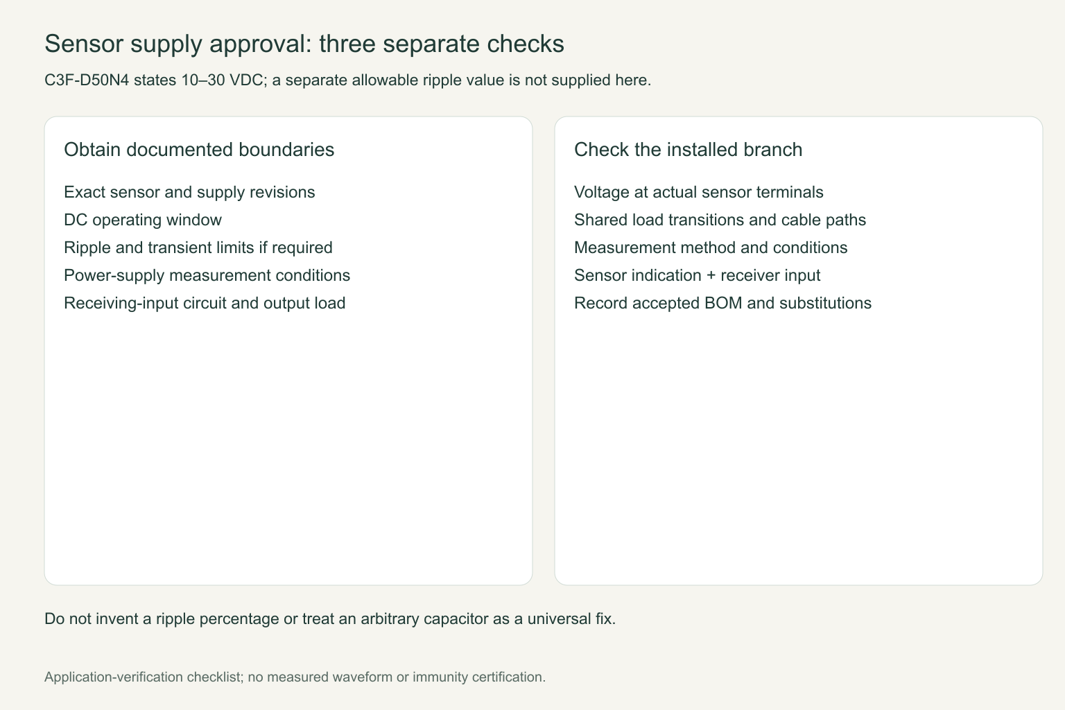
The WEHO C3F-D50N4 documentation specifies a 10–30 VDC supply. The matched sheet available for this model does not state a separate allowable ripple percentage or a millivolt peak-to-peak limit. Do not turn that absence into “any ripple is acceptable,” or borrow a limit from another sensor family.
Why a nominal 24 V supply is only the first screen
The sensor’s stated DC range is a useful selection boundary. It is not a complete noise-immunity specification. Supply tolerance, load-dependent drop, wiring resistance and dynamic events all affect the voltage at the sensor rather than at the power supply’s terminals. A cabinet drawing that shows 24 V on one rail does not describe the worst voltage during a solenoid operation or a machine restart.
Specify the operating conditions that the OEM must assess: minimum and maximum incoming supply, shared loads, cable length, connector arrangements and startup or shutdown behavior. Ask for the exact sensor revision’s ripple and transient requirements if those details are needed to approve the design. Require the power-supply ripple specification together with its measurement conditions; a bare number without load, bandwidth and probe method can be misleading.
Distinguish ripple from a shared-return problem
| Observed behavior | Evidence to collect |
|---|---|
| Periodic variation on an otherwise steady DC level | Waveform, load state, measurement bandwidth and measurement point at the sensor. |
| Short dip or spike when another device switches | Timing relative to the load event, local supply and return voltages, and the shared wiring path. |
| Controller changes state without an intended target | Sensor indication, output voltage and controller input state together; also rule out target movement and background effects. |
| Only one long cable run is affected | Voltage at both ends under the same load, connector condition and return-path layout. |
These observations help the integrator decide what to investigate; they do not identify a cause by themselves. Do not fit an arbitrary capacitor at the sensor as a universal remedy. Added capacitance, filtering and surge suppression need a documented design compatible with both the sensor and the supply.
Check the output interface separately from the supply
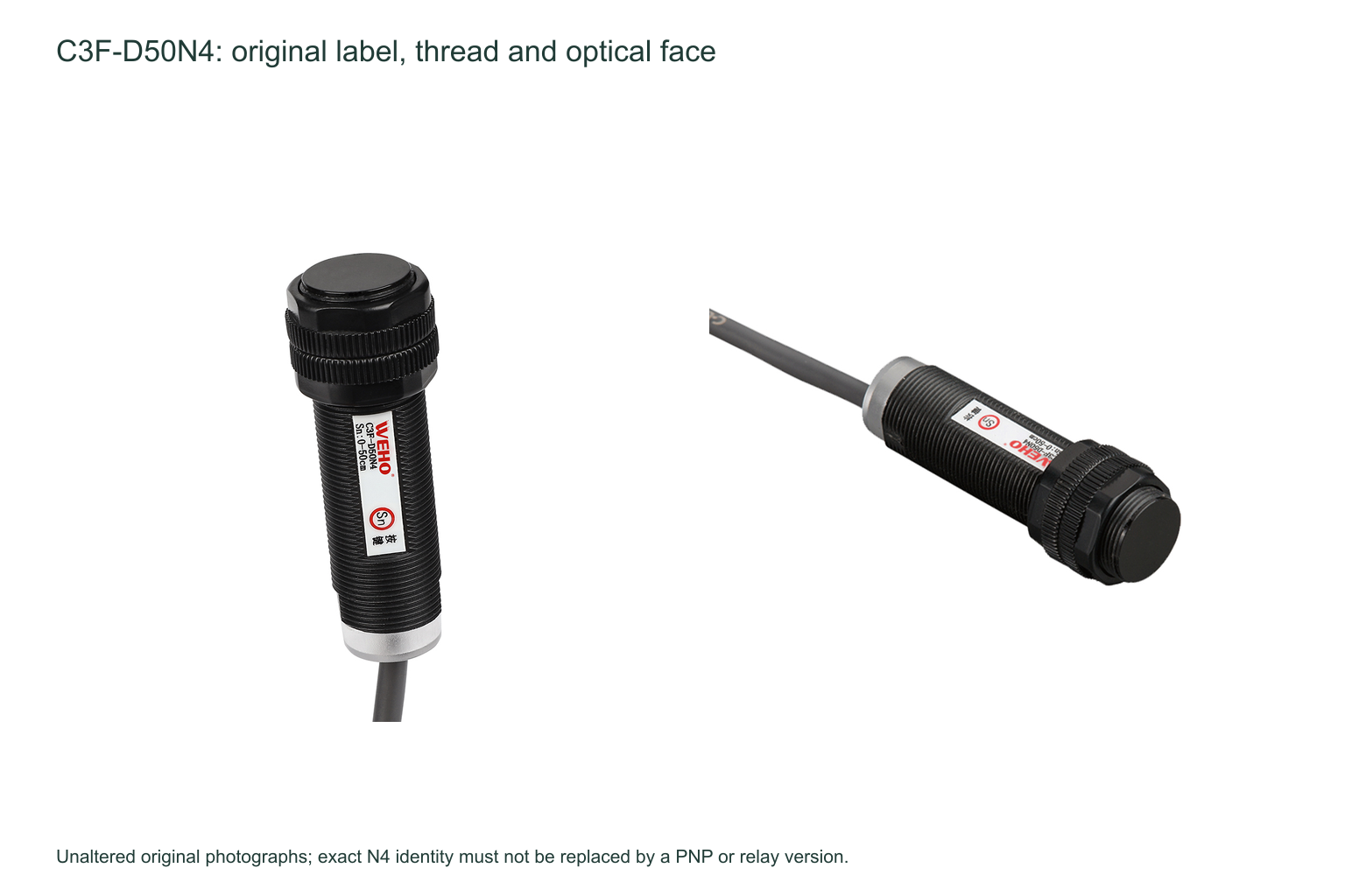
C3F-D50N4 is the NPN NO+NC version. Its matched sheet assigns brown to positive supply, blue to 0 V, black to NO and white to NC; it gives a maximum output load of 200 mA and a residual voltage of no more than 2 V. A stable DC supply cannot correct a mismatched controller input, an incorrect output selection or an overloaded output.
Document the receiving input circuit and the reference connection, not merely a wire-color list. The installer should preserve the equipment’s required separation and routing arrangements, use appropriate strain relief, and verify the complete circuit against the controller instructions. Do not use a sensor’s small output as a power feed for an actuator.
Turn the noise question into a sample-acceptance plan
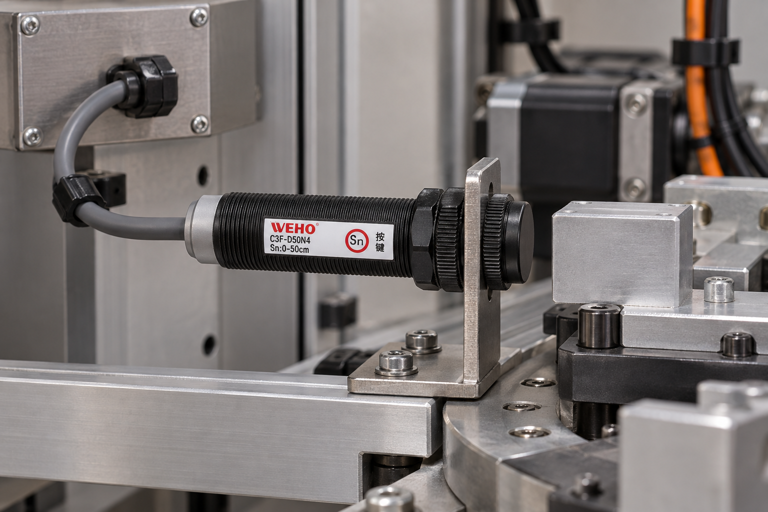
For a repeated machine build, require observations at the actual sensor connection during representative worst-case operations. Record the measurement instrument and method, machine load sequence, cable configuration and exact sensor and supply versions. Compare the result with documented limits; if a necessary limit is absent, obtain clarification before declaring compliance.
Repeat the target-present and target-absent checks while the relevant machine loads operate. A clean-looking trace without a correct input response is not sufficient, and an apparently correct count over a short trial is not evidence of an unspecified immunity rating. Keep the acceptance record linked to the bill of materials so that a lower-cost supply substitution triggers a review of its dynamic behavior, not only its nominal wattage.
Questions for a purchasing review
Does the 10–30 VDC range permit any 24 V switching supply?
No. It identifies the stated DC operating range. Output conditions, wiring, environmental requirements and the receiving circuit still need an application check.
Can a ripple limit from another sensor be applied to C3F-D50N4?
No. Obtain a limit for the exact model and revision, with the relevant conditions. The present C3F sheet does not supply that separate value.
For an OEM inquiry, send WEHO the supply model, sensor quantity, cable lengths, shared loads, controller input and the event that must be tolerated. Request the relevant sensor documentation and use the contact form to resolve missing ripple or transient criteria before sample approval.




