

Key Engineering Takeaways
- A grounded thermocouple junction can connect the measurement circuit to the conductive sheath and process.
- A differential input does not automatically provide galvanic isolation or unlimited common-mode range.
- Review input-to-power, input-to-earth and any channel or communication boundaries separately.
- Choose the probe and interface from a documented path review; preserve protective earth throughout diagnosis.
Map the conductive path before changing the probe
A thermocouple can produce a plausible differential signal while its conductors sit at an unsuitable potential relative to the receiving instrument. Changing an offset may hide one observation without correcting that interface. Identify the junction construction, process contact and controller input architecture before deciding whether a grounded or ungrounded probe is appropriate.
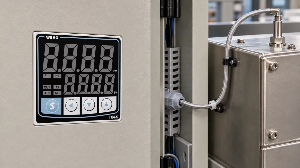
The WEHO TX4-S temperature controller is the process-controller reference shown here. Match its complete configuration and applicable instructions to the received unit. The photograph identifies hardware; it does not establish input isolation, permitted working voltage or compatibility with an electrically energized surface.
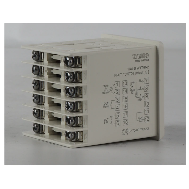
For thermocouple type, extension materials and polarity, use the existing TX4 K-type measurement-chain article. The additional task in this article is to determine which conductive paths connect the sensing junction, sheath, process, receiver and other equipment, and which documented boundaries interrupt them.
Distinguish junction construction from the controller input
A grounded junction is electrically connected to its conductive sheath. An ungrounded junction is insulated from the sheath by the probe's construction. An exposed junction has another physical arrangement whose electrical contact with the process depends on the installation. Obtain the probe manufacturer's construction and insulation information rather than assigning a junction type from the cable color or metal tip alone.
The controller has a separate set of properties. A differential input measures a voltage between two terminals, while galvanic isolation concerns conductive separation across a specified boundary. NI's measurement-noise guidance describes how a grounded thermocouple source and receiver at different potentials can create a ground loop even in a differential measurement.
An ungrounded probe does not remove every installation dependency. Its insulation has temperature, environmental and voltage limits, and other circuit connections may still define the input reference. Follow the receiver's instructions for floating sources and any required bias path. Do not add an improvised grounding resistor or bond because a different instrument's example uses one.
Request isolation information for each actual boundary
The word “isolated” needs a destination. Input-to-power isolation does not necessarily mean channel-to-channel isolation; an input-to-case test does not automatically describe either. Include external recorders, computers, communication converters and shared supplies in the review wherever they are actually connected.
NI's isolation-specification guidance separates working-voltage and isolation considerations from the small differential signal range. Use the same discipline when requesting a controller interface: name the two circuits being separated, the applicable voltage conditions and the evidence supporting the claimed boundary.
| Boundary or path | Question to resolve | Evidence to retain | Effect on the decision |
|---|---|---|---|
| Junction to sheath/process | Does the sensing circuit contact the conductive process? | Probe construction and applicable insulation data | Defines a possible source reference and current path |
| Input to controller supply | Is the input separated from its power circuit? | Exact model isolation and working-voltage information | Determines whether supply connections introduce another path |
| Input to other channels | Can separate probes sit at different potentials? | Channel architecture and allowed differences, if applicable | Determines whether multi-point measurement is supported |
| Receiver to external equipment | Does a recorder or communication link change the reference? | Complete interface diagram and equipment specifications | May introduce a path absent during standalone operation |
The TX4 manual, 230808EN gives a dielectric-strength test between all terminals and the case. That grouped test statement does not provide a complete input-to-supply isolation specification. Ask for the particular boundary needed by the project; do not convert a short-duration withstand figure into a continuous operating voltage.
Use a hypothetical common-mode check to identify a gap
The following numerical example explains the interface calculation. It is not a TX4 specification, a safe-touch-voltage assessment or a recommendation to probe energized process equipment. Assume a receiving instrument's documentation permits a common-mode range of ±2.5 V under the stated conditions.
In an assumed observation referenced to that instrument's specified common, the positive input is at 4.010 V and the negative input is at 3.990 V. Calculate the differential quantity:
Differential voltage = 4.010 V − 3.990 V = 0.020 V = 20 mV.
Calculate the common-mode quantity for this simplified input model:
Common-mode voltage = (4.010 V + 3.990 V) ÷ 2 = 4.000 V.
The differential signal is only 20 mV, but the assumed common-mode level exceeds the +2.5 V limit by 1.5 V. The review therefore rejects this interface condition. A plausible thermocouple-scale differential voltage does not resolve the excess reference voltage. Actual instruments may specify additional pin-to-common, pin-to-earth and transient restrictions that also require checking.
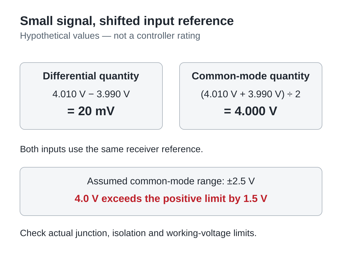
Swipe horizontally on a small screen, or open the full-size diagram.
Do not calculate a temperature from this example to decide whether the interface is acceptable. Thermocouple conversion depends on type and reference-junction compensation, while the failed check concerns an electrical input limit. Fix the interface question first, then verify temperature accuracy over the required process range.
Compare solutions by the path they actually change
A probe with an insulated junction may interrupt the intended junction-to-sheath path, provided its construction and ratings suit the process. A suitable isolated input or signal conditioner may separate specified circuits instead. Each option introduces its own limitations, including insulation conditions, signal conversion, accuracy contribution and response behavior. Compare complete documented arrangements.
Do not assume that filtering provides isolation. A filter can change how a disturbance appears without eliminating the conductive path responsible for it. Likewise, selecting a slower display response may make a trace look calmer while leaving an electrical limit exceeded. Retain both the electrical acceptance conditions and the temperature-performance requirements.
For the illustrated TX4-S controller configuration, request the exact interface information before selecting any external conditioner. The conditioner output must match a supported controller input. A suitable thermocouple input on one side does not establish a compatible signal on the other side.
Verify the complete installed measurement chain
Begin with a controlled inspection and documented measurement plan appropriate to the equipment's energy sources. Qualified personnel should choose instruments and methods rated for the potential differences involved. Preserve protective bonding; disconnecting protective earth is not a measurement-noise remedy.
- Identify the junction and process contact. Record probe model, junction construction, sheath attachment and any conductive process connection. Verify these against the probe documentation and installation rather than relying only on a continuity observation.
- Map the receiving circuits. Record the exact controller model, supply, input, any other channels and connected external equipment. Verify the required isolation and working-voltage boundaries from their respective instructions.
- Review normal and changed configurations. Record standalone operation, recorder or communication attachment, heater/drive switching and relevant power states. Verify that the reviewed path diagram represents every configuration used in production or service.
- Check electrical and temperature acceptance separately. Record the approved electrical observations, measurement references and process comparison points. Verify both input-limit compliance and temperature performance against predeclared requirements, including uncertainty where relevant.
- Release the documented combination. Record probe, controller, conditioner and wiring revisions with the results. Repeat affected checks when a substitute probe changes junction construction or a new external connection changes the reference paths.
A useful acceptance record can conclude “interface data required” rather than choosing a probe by preference. If the needed isolation boundary or common-mode allowance is unspecified, obtain the missing evidence or select an arrangement with documented suitability. A successful room-temperature display alone does not close that gap.
Send the isolation-path requirement with the enquiry
Ask WEHO for the applicable TX4 input information for the exact ordered configuration. Include thermocouple type, grounded or insulated junction construction, process contact, supply arrangement and any connected recording equipment. State the electrical separation and temperature-performance requirements so the review addresses the complete measurement interface.
Engineering FAQ
Does a differential thermocouple input mean the input is isolated?
No, differential measurement and galvanic isolation describe different properties. Check the specified separation between input, supply, earth and any other channels. The instrument's permitted common-mode range also applies and cannot be inferred from its thermocouple measurement range.
Can an ungrounded thermocouple eliminate every ground loop?
An ungrounded junction does not guarantee elimination of every loop in the installed system. Probe insulation, shields, input references and external equipment still need review. Use the probe and receiver instructions to establish the complete conductive path.
Does a high dielectric test voltage establish continuous input working voltage?
No, a short-duration withstand test is not a continuous working-voltage rating. Confirm the named circuits, test conditions and allowed operating voltage separately. A test between grouped terminals and the case does not prove every internal boundary is isolated.
Can an input offset correct noise from an unsuitable ground path?
An offset cannot establish electrical compatibility or remove a conductive path. Diagnose the reference, common-mode conditions and interference before adjusting calibration. Recheck measurement accuracy after the interface is corrected instead of using a constant offset to conceal changing errors.
Should protective earth be disconnected to reduce thermocouple noise?
Protective earth must remain as required by the equipment's safety design. Resolve measurement problems through documented probe construction, suitable input isolation, compatible interfaces and correct installation. Any signal-reference change must preserve the equipment's protective measures.