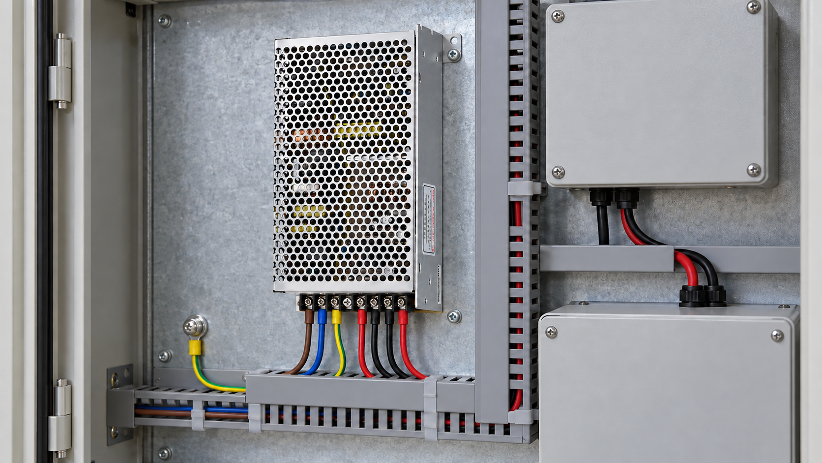
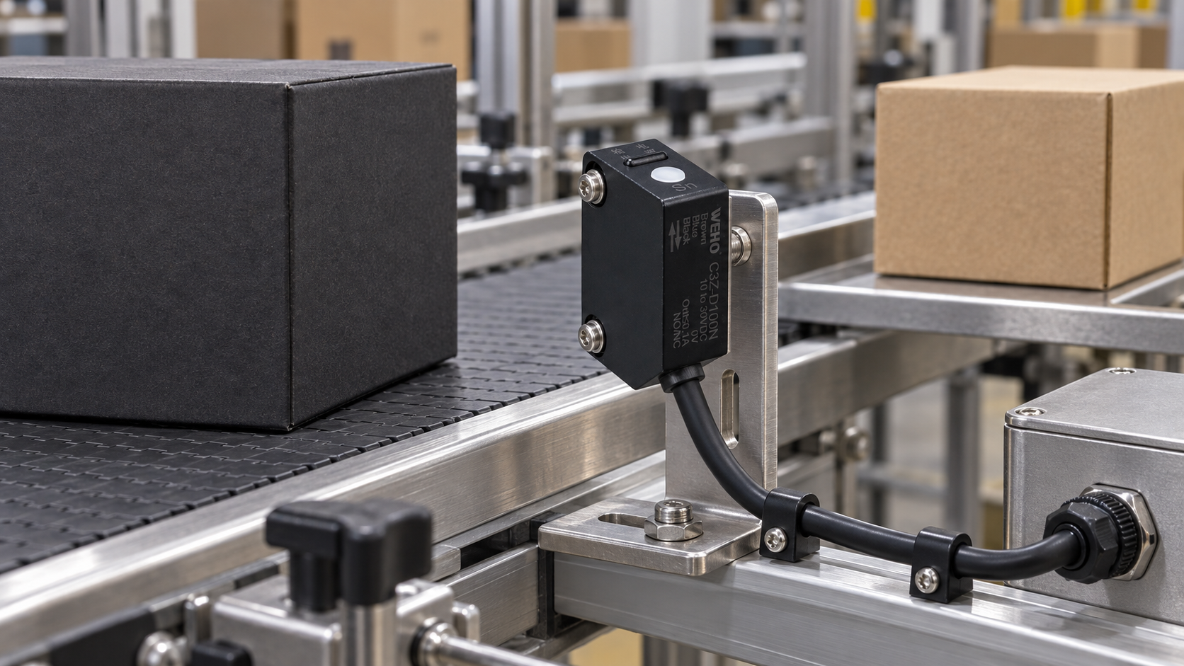
A temperature controller’s response to an open or shorted sensor depends on the input technology, the specific fault, the controller and its configuration. Record the expected display, control output and equipment behavior for each relevant fault; do not assume every break or short produces the same alarm or safe output.
Define each fault and the equipment response
OMRON’s E5C2 FAQ gives a real example: output behavior varies with thermocouple, resistance thermometer or thermistor input and the fault involved. Those outcomes are specific to that model and must not be transferred to a WEHO controller.
If uncontrolled heating or another failure can harm people or equipment, the responsible machine designer must define the independent protective functions and verification needed for the application. A standard controller alarm is not automatically an independent safety function.
Identify the measurement and output chain
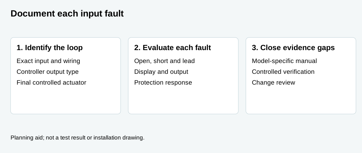
Record the exact controller ordering code, power and output type, firmware or hardware revision where relevant, selected input type and settings, probe and lead arrangement, final receiving actuator and the separate protective devices. A relay or SSR drive output must be interpreted through the actual external circuit and actuator; an indicator on the controller alone does not establish the final equipment state.
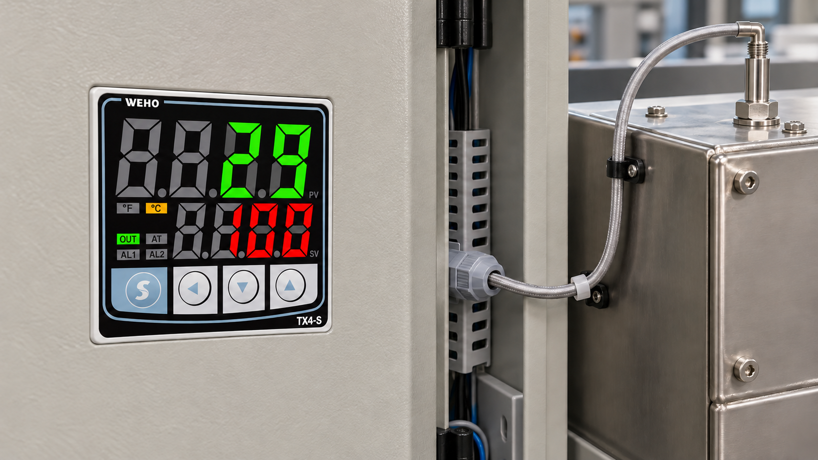
The TX4-S product page identifies thermocouple and RTD inputs and output options. The pictured TX4-S application scene illustrates a normal installation context; it does not demonstrate a sensor fault test or verified equipment response. Obtain the latest exact-version instructions and ask WEHO for the relevant fault behavior before writing acceptance criteria.
Make each fault a separate scenario
Start with the input used in the actual design. Possible cases include an open sensing element or lead, a short between conductors, and—for multi-wire RTD arrangements—the individual conductor faults the application must cover. Some incorrect measurements can appear plausible; do not assume a shorted thermocouple necessarily produces an obvious open-sensor alarm.
For each case, document the expected and observed display, controller output, external actuator state, alarm indication, reset behavior and independent protective response where applicable. Record “not verified” where the exact model instructions do not specify a behavior. Include connection and sensor substitution faults when the machine risk analysis calls for them.
Read the manual within its scope
The published TX4 instruction manual includes safety considerations and calls for a fail-safe device in specified high-consequence machinery. Confirm that the manual revision and complete ordering code match the product being purchased. A product-family manual and a photograph do not by themselves document the complete response of every sensor fault in every output configuration.
Distinguish an out-of-range display from a verified diagnosis of a specific wiring fault. Ask the manufacturer whether the exact input, wiring and setting are monitored, how fault indications map to each output, and what conditions or limitations apply. Do not assign the behavior of another manufacturer or another controller variant to TX4.
Prepare a fault-response matrix
| Scenario | Information to record | Required evidence |
|---|---|---|
| Normal input | Probe type, wiring, range, controller state and target output. | Baseline equipment function in the approved configuration. |
| Open input | Exact element or conductor and when the fault occurs. | Display, controller output, final actuator and reset behavior. |
| Shorted input | Exact conductors or sensor location involved. | Whether it is detected and what the equipment actually does. |
| Other relevant wiring faults | Specific RTD lead, probe mismatch or loose connection. | Manufacturer information and project-specific verified response. |
| Protective function | Independent protection and responsible review. | Separate evidence of intended protective behavior. |
This is a proposed acceptance record, not a fault-response table for TX4 or a complete safety assessment.
Plan verification without creating an uncontrolled hazard
Have qualified personnel prepare a procedure based on the equipment risk assessment, manufacturer instructions and safe test conditions. Specify how the test state is established, how unintended energy is prevented, what is monitored, who can stop the test and how normal operation will be restored. Do not disconnect or short a live sensor merely because a checklist says to test it.
If the machine uses a heater, record the actual controlled output and final actuator independently; a displayed code may not reveal a stuck contact, an incorrectly configured drive or failure elsewhere in the chain. Preserve time-aligned observations and identify missing evidence. The designated safety specialist determines the test and independence requirements.
Close gaps and control changes
A hypothetical machine uses an RTD input and the owner has evidence for a broken element but none for a lead fault. Mark the latter as unverified and obtain the controller and probe documentation; arrange a project-specific assessment before release. Do not label the whole system safe because one fault case behaved as expected.
Revisit the matrix after changing the controller, sensor, wiring, output device or control settings. Save the accepted configuration and tested responses with the maintenance instructions.
Questions buyers ask
Will every sensor open circuit turn the heater off? Not universally. Check the exact sensor, controller and output configuration and verify the final equipment response.
Does a temperature alarm replace an independent protective device? Not automatically. The machine’s risk assessment and applicable requirements determine the protective architecture.
Can OMRON E5C2 fault behavior be used as a TX4 fault table? No. It illustrates why model-specific information is necessary.