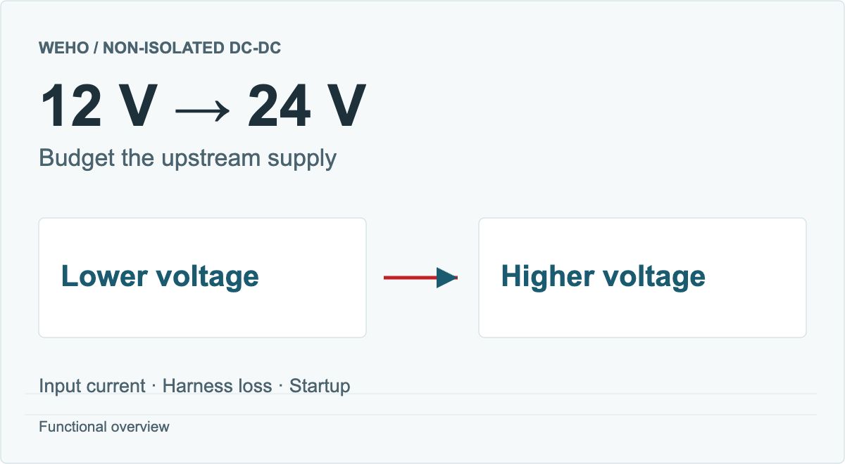
A 12 V to 24 V converter can draw substantially more input current than its 24 V output current. For a continuous load, start with output power, divide by an explicitly assumed or verified efficiency, and divide again by the voltage measured at the converter input. Then add the upstream requirements of the harness and any other loads.
For a 24 V, 5 A, 120 W class candidate such as the WEHO WH-B122405, first check the actual source envelope and required load. The budget below defines continuous upstream demand; startup, faults, usable output at each condition and the exact assembly documentation remain separate checks.
Article sections
Separate input current from output current
Power balance is the starting point: Pout = Vout × Iout, Pin = Pout ÷ η, и Iin = Pin ÷ Vin, where η is efficiency expressed as a decimal. These quantities describe the same steady operating point.
For example, even an ideal lossless converter delivering 24 V at 5 A transfers 120 W and needs 10 A from a 12 V input. Real conversion loss increases the required input power. The output-current number therefore cannot be copied directly into the upstream source specification.
Device-level current limits need their own interpretation. TI’s boost-current application brief explains that an IC’s input/switch-current limit is not simply its output-current capability. That distinction is useful when reviewing a complete module, but it does not identify the components or current-limit behavior inside a WEHO assembly.
Calculate the continuous upstream budget
Hypothetical load case: an equipment rail requires 24 V at 4 A continuously, so output power is 96 W. Assume 90% efficiency for the calculation only. Required converter input power is 96 ÷ 0.90 = 106.67 W, with 10.67 W conversion loss. No measurement or model-specific efficiency curve is implied.
| Voltage at converter input | Assumed efficiency | Output load | Calculated mean input current |
|---|---|---|---|
| 10.0 V | 90% | 24 V × 4 A = 96 W | 106.67 W ÷ 10.0 V = 10.67 A |
| 12.0 V | 90% | 24 V × 4 A = 96 W | 106.67 W ÷ 12.0 V = 8.89 A |
| 16.0 V | 90% | 24 V × 4 A = 96 W | 106.67 W ÷ 16.0 V = 6.67 A |
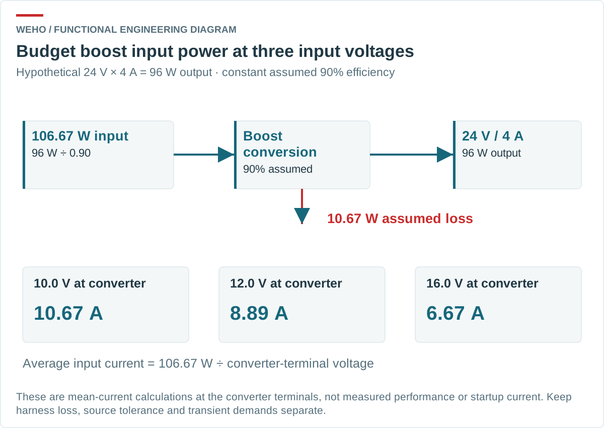
The lower-voltage point creates the largest current in this fixed-power example. TI’s Basic Calculation of a Boost Converter’s Power Stage likewise uses minimum input voltage when assessing maximum switch-current requirements. The table above is a system power-budget illustration; it does not prove a particular module delivers 96 W throughout the listed range.
Replace the assumed efficiency with applicable measured or documented data when it becomes available. If the project load has several states, retain separate rows for each continuous state instead of using one favorable efficiency or an average output current to approve every condition.
Include harness loss at the correct boundary
Use converter-terminal voltage in the converter calculation. Source-terminal voltage can be higher because the connecting path has resistance. Connector contacts, protection elements, and both outgoing and return conductors belong to that upstream path.
Continue the hypothetical 12.0 V converter-input case. With calculated input current 8.8889 A and an assumed total harness-loop resistance of 0.050 Ω, the harness drop is I × R = 0.4444 V. The source must provide approximately 12.4444 V to leave 12.0 V at the converter at that current. Harness loss is I² × R = 3.95 W.
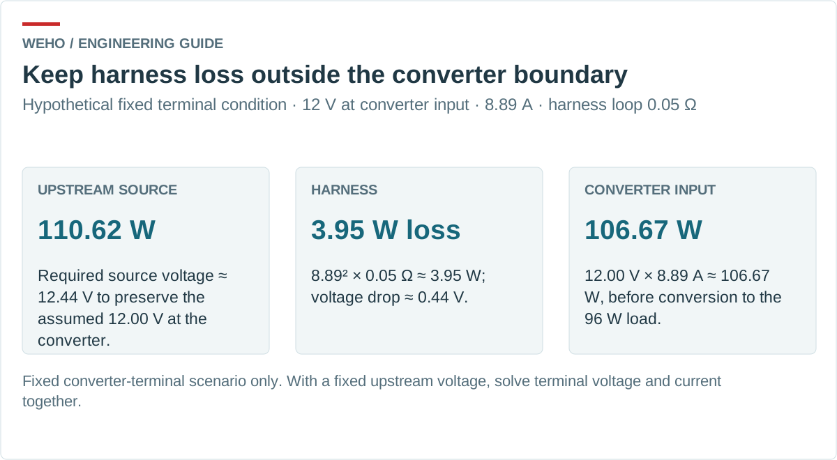
The source supplies approximately 106.67 + 3.95 = 110.62 W for this branch, before any other upstream losses or loads. Keep the two losses separate: 10.67 W is the assumed converter loss and 3.95 W is the assumed harness loss. Counting both is appropriate; counting either twice is not.
Apply the same static hypothetical check at 10.00 V converter terminals. With 96 W output and assumed 90% efficiency, input current is 10.6667 A. Across 0.050 Ω, the drop is 0.5333 V and harness loss is 5.6889 W. The arithmetic source voltage is therefore 10.5333 V to leave exactly 10.00 V at the converter. This is a zero-headroom calculation, not an approved minimum source voltage: source tolerance, temperature, connections, startup and transients require their own allowance and evidence.
If the source instead remains fixed, converter-terminal voltage and current must be solved together or measured. For a battery supply, define its real operating input envelope before applying the budget. A nominal battery label does not resolve the interaction between voltage, load current and cable loss.
Review the WH-B122405 model record separately
А WEHO WH-B122405 product detail lists a non-isolated step-up converter with a 10–16 V input range and a nominal 24 V, 5 A, 120 W output. The linked WH-B122405 specification file lists 93% efficiency, but the reviewed material does not provide the input/load/temperature curve needed to apply that figure across the operating range. The article’s 90% assumption is separate and is not a replacement specification.
There are also document differences to resolve before assembly selection. The PDF prints the shorter model WH-B2405. The webpage describes three leads with a shared negative, while the PDF lists four leads. The PDF’s general dimensions are 75 × 75 × 32 mm, but its installation drawing labels 74 mm in both plan directions. These differences must not be silently converted into an authoritative wiring or mounting drawing.
Both sources state non-isolated; separate negative leads do not establish galvanic isolation. Obtain the controlled harness and mechanical drawing for the offered build. Determine current in each conductor from the actual connection nodes and current directions; do not add input and output current labels to assign a shared lead’s rating. The common-negative return-path review explains why the connected network matters.
Separate steady load, startup, and fault demand
Mean input-current arithmetic does not capture every upstream requirement. Record the converter and load startup sequence, any required load steps, low-voltage behavior, source current limit, and permitted equipment recovery. Obtain the corresponding waveforms or agreed test records when those behaviors determine selection.
Do not turn an assumed percentage margin into evidence that startup will succeed. A source that can continuously deliver the calculated watts may still respond differently during a transient; the complete source, harness, converter, and load configuration must be assessed together.
The WH-B specification calls for a 20 A input fuse in its short-circuit-protection information. That line does not approve every 20 A fuse or establish the complete branch design. Ask for the applicable fuse type and coordination requirements, then verify the device’s DC voltage/interruption capability, source fault conditions, conductor protection, and time-current behavior. This article’s continuous-current budget does not select a fuse.
Request an upstream supply review
Send WEHO your 12 V to 24 V converter power budget with the following linked records:
- Source-voltage limits and where they are measured.
- Continuous/transient load states and the harness-loop budget.
- Intended mounting, temperature, startup and recovery conditions.
- Exact build, controlled harness/mechanical drawings, and applicable protection requirements.
A useful upstream specification keeps continuous current, transient demand, and fault protection in separate fields. That allows the source and harness to be compared on the same conditions while the converter’s model and assembly differences are resolved explicitly.