When comparing a linear regulator vs buck converter, start with the required input voltage, output voltage and load current. A linear stage dissipates approximately the input-to-output voltage difference multiplied by load current. A buck stage has switching and conduction losses that must be evaluated at the operating point.
A large voltage reduction at sustained current often makes the linear stage’s dissipation the first constraint. A small voltage difference and light load can lead to another choice. Neither architecture is automatically suitable for every rail. The useful result is a topology shortlist with explicit loss, headroom, noise and installation requirements.
Article sections
Put both alternatives on the same load requirement
Write down input minimum/maximum, output tolerance, continuous current and relevant load changes. Compare identical delivered output power. This article addresses equipment-level power stages. A board-level IC comparison must also include its external parts, layout and PCB thermal design; a packaged buck module should be compared with the complete linear assembly, including its necessary heat removal and protection.
A fair assembly comparison includes required external parts, protection, mechanical support and heat removal. Also identify the reference: the choices here are non-isolated step-down stages. Neither an ordinary linear regulator nor a non-isolated buck stage provides an input-to-output galvanic barrier.
Record what would disqualify an option before selecting parts: unacceptable dissipation, insufficient regulation headroom, an unsupported input condition, or a noise requirement that the proposed implementation cannot demonstrate. Those gates make the comparison useful to procurement rather than a list of general advantages.
Calculate a 24 V to 12 V, 2 A example
Assume a hypothetical continuous load of 12.00 V at 2.00 A supplied from 24.00 V. Ignore linear-regulator ground current for this first-pass comparison. The output power is 24.00 W. Linear-stage loss is(24.00 − 12.00) × 2.00 = 24.00 W, so input power is 48.00 W and approximate efficiency is 50%.
Now assume a buck stage operates at 92% efficiency at exactly this point. Its input power is 24.00 ÷ 0.92 = 26.09 W and loss is 26.09 − 24.00 = 2.09 W, rounded. The 92% is a scenario assumption, not a WEHO measurement or a universal buck-converter value.
| Same 12 V, 2 A load | Linear stage, simplified | Buck stage, assumed 92% |
|---|---|---|
| Выходная мощность | 24.00 W | 24.00 W |
| Input power | 48.00 W | 26.09 W |
| Conversion loss | 24.00 W | 2.09 W |
| Resulting design question | Can the assembly remove 24 W under the specified conditions? | Can it reproduce the assumed loss while meeting the other requirements? |
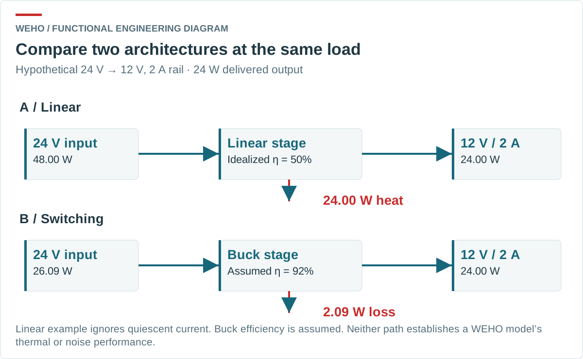
Analog Devices AN-140 explains the linear loss relationship and the two architectures. Here the arithmetic gives a reason to investigate buck conversion. It does not determine a heatsink, prove a case temperature or approve a particular product.
Reconsider the answer at light load and small voltage difference
A second hypothetical condition shows why the conclusion needs its boundary. At 13.00 V input, 12.00 V output and 0.10 A load, the simplified linear loss is 0.10 W. Ignoring ground current, efficiency is 12 ÷ 13 = 92.3%. That may be a manageable loss, depending on the regulator and thermal arrangement.
But regulation still requires enough headroom at the minimum input and maximum relevant load. A low-dropout regulator has a model-specific dropout requirement. Its ground current, temperature behavior and reverse-voltage conditions also matter; a nominal 1 V difference is not an approval.
Analog Devices’ LDO efficiency comparison discusses how a small input-to-output difference can change the tradeoff. No buck-efficiency value is assumed for this second scenario, so it does not declare either architecture the winner.
Compare noise and operating behavior separately from watts
Power loss narrows the choice; it cannot establish noise compatibility. Specify the sensitive circuit’s allowed rail disturbance and the measurement conditions. A buck stage switches, while a linear stage has its own noise and frequency-dependent rejection behavior. Judge the implemented rail, not an architecture label.
A buck followed by a linear stage may be a candidate where appropriate, but the intermediate voltage must leave sufficient linear-stage headroom during the required input and load conditions. Count both stages’ losses and verify startup and stability with the selected components. Adding a linear stage does not automatically eliminate every disturbance.
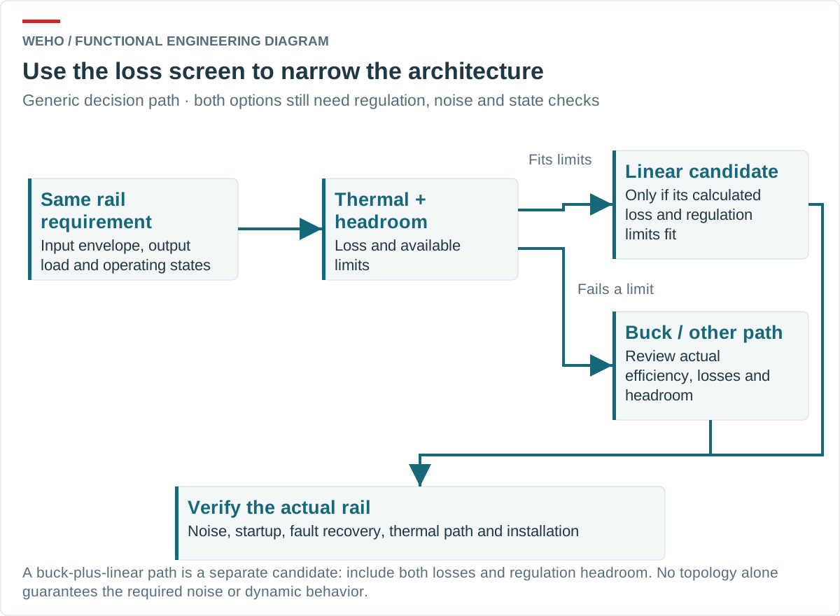
Review startup load, output capacitance, shutdown state, fault response and possible externally driven outputs as separate requirements. Neither the loss calculation nor a larger current rating establishes those behaviors. Keep any required isolation as an independent system requirement; it is outside this non-isolated comparison.
Translate the loss estimate into an installation review
Document where the generated heat can go: semiconductor package or converter case, mounting surface, board copper where applicable, enclosure and surrounding air. Use the applicable component or assembly thermal data and verify the actual arrangement. A bare linear IC’s thermal figure cannot be applied to a packaged buck converter.
Record ambient and temperature measurement locations independently. Verify the required load at the relevant environmental conditions and identify any manufacturer limits or derating conditions. A touch impression is not a quantified thermal result, and an enclosure’s spare space does not define its cooling capacity.
For purchasing, compare complete proposals with equivalent electrical and environmental requirements. Include the additional parts and installation obligations in each proposal, rather than assume a lower part count or lower nominal loss produces the lowest finished-equipment cost.
Review WH-C241210 as a packaged buck candidate
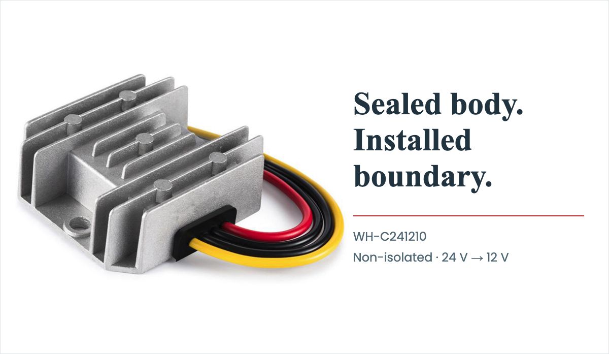
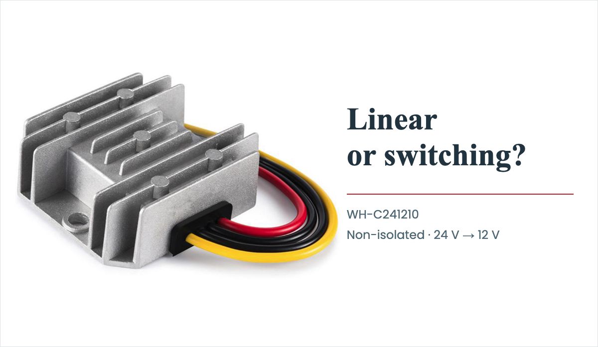
А WEHO WH-C241210 product details identify a non-isolated 24 V to 12 V converter with a published 18–32 V input range and 12 V, 10 A, 120 W output rating. Its exact-model specification PDF is a starting point for reviewing the buck assembly in a 24 V to 12 V design.
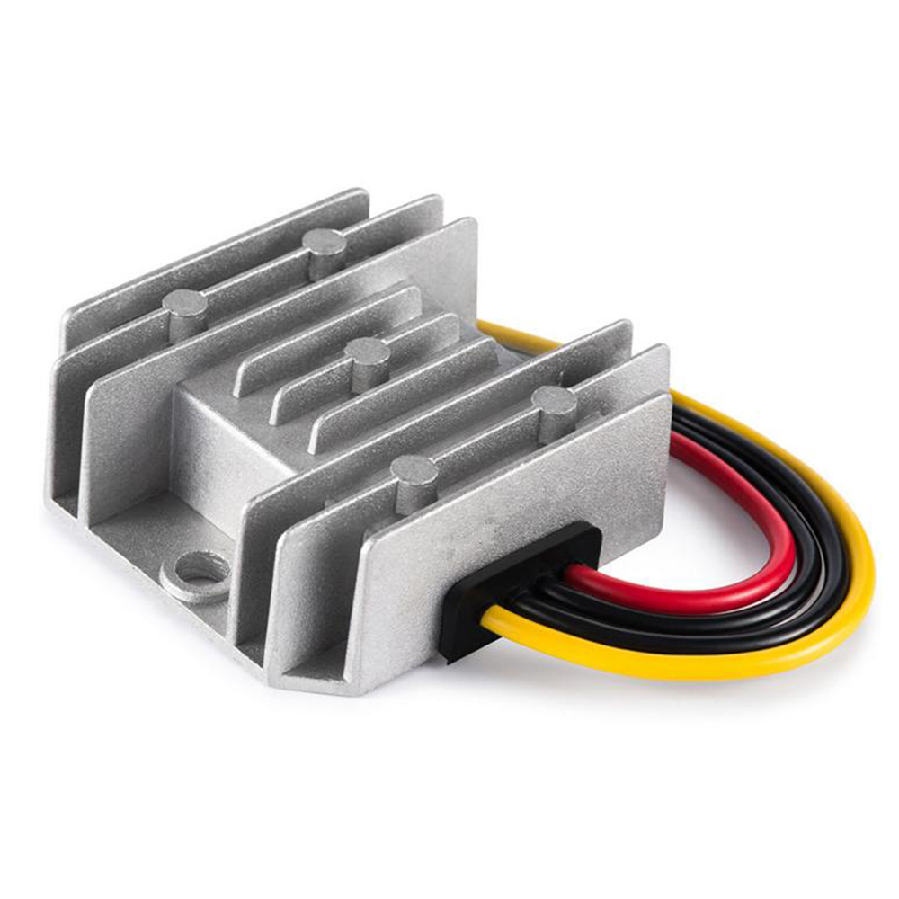
The 2 A example represents 2 A ÷ 10 A = 20% of this model’s nominal current rating, or 24 W ÷ 120 W = 20% at 12 V. That arithmetic does not determine its efficiency. Request applicable partial-load data at the intended input and thermal conditions, and ask whether a lower-current 24 V to 12 V build better matches the rail. The published 96% figure does not establish the assumed 92% or any other value at this point.
This product is not the generic linear stage in the comparison. The 13 V-input light-load example is outside its 18–32 V range. To compare operating-point evidence, use the DC efficiency and measurement-boundary method.
The document’s 45 °C rated temperature-rise row is not an ambient limit. Obtain the relevant thermal conditions and limits. If the assembly also needs environmental sealing, use the converter, harness and enclosure installation-boundary review alongside the power-loss assessment.
Send a topology requirement that can be compared
Send WEHO the DC conversion and installation requirements for your equipment, включая:
- Input envelope, output load and duty.
- Acceptable loss and noise criteria.
- Space, mounting and environment.
- The required partial-load point, such as the 2 A example, and its applicable efficiency and thermal evidence.
Ask which exact buck assembly can be evaluated against that specification and what evidence remains to be obtained. Keep any linear-stage alternative under the same load and environmental assumptions. The resulting comparison supports a defensible architecture decision without treating a hypothetical heat calculation as product qualification.