Key Engineering Takeaways
- A faster display update cannot remove the thermal lag of a probe or its mounting.
- Compare response-time claims only when the percentage criterion and test conditions match.
- A hypothetical 20-to-100 °C step reaches its 63.2% point at about 70.6 °C.
- Record the TX4-S configuration and the complete probe assembly before deciding what to change.
Why Can a Temperature Reading Arrive Late?
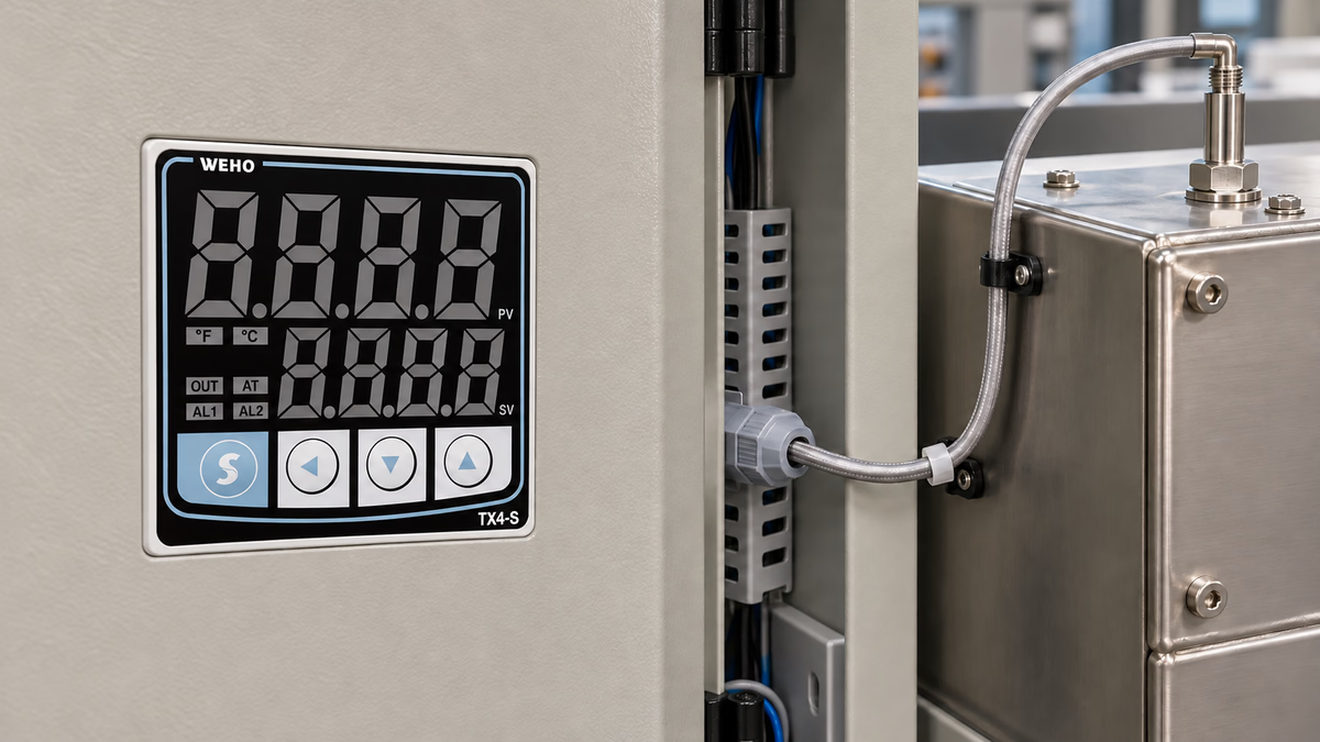
A machine can develop a real temperature change before its temperature probe reports the full change. Heat must pass through the installed probe assembly, and the measuring junction has thermal mass. The controller then processes the input and presents a value. These stages should be investigated separately before a team orders a different controller to solve an unidentified delay.
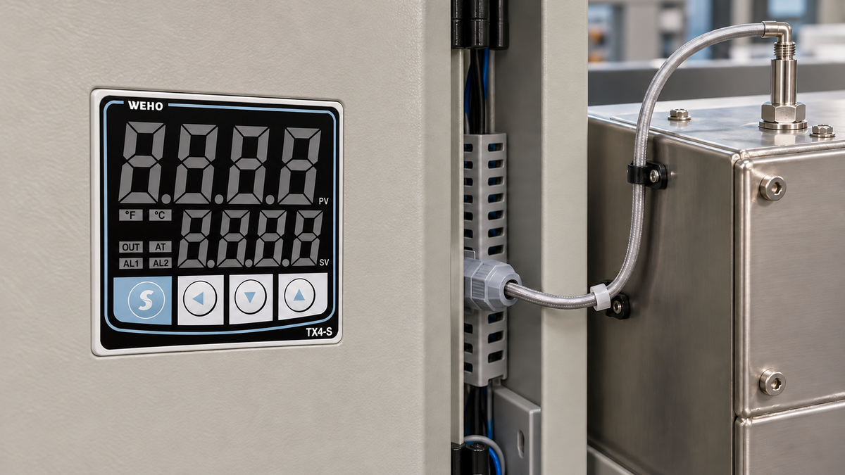
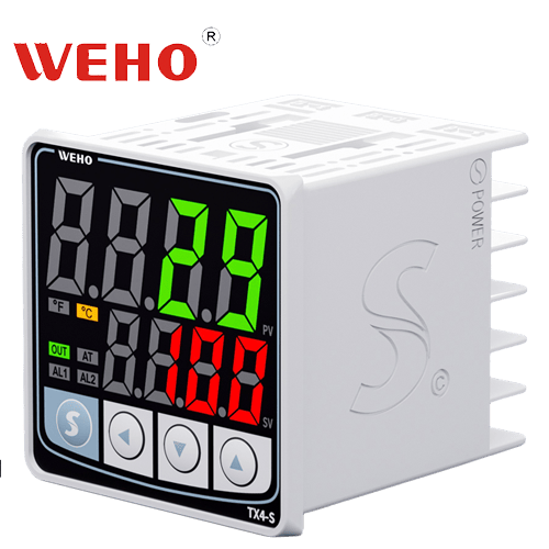
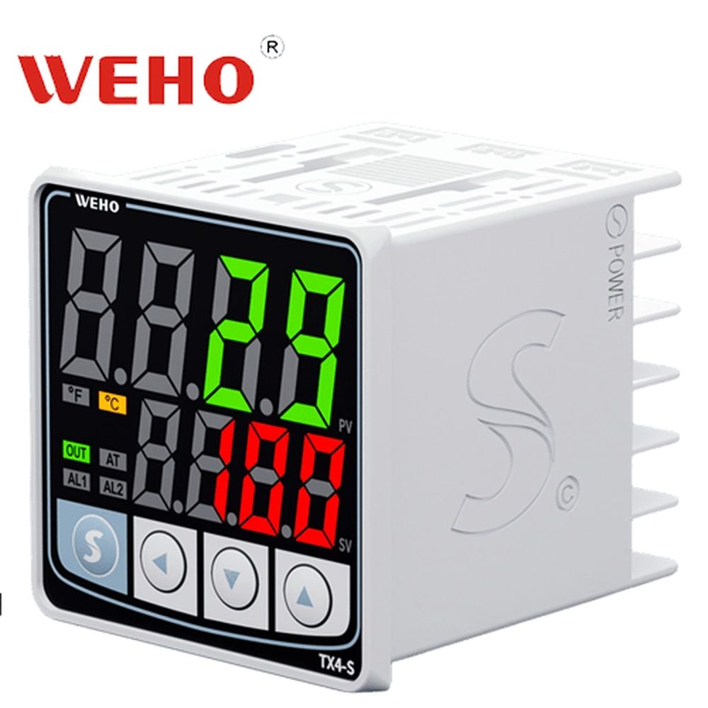
ที่ TX4-S temperature controller is the product reference here. The engineering task is to distinguish probe response from controller and observation timing. This article does not assign an undocumented response time to a TX4-S unit or to the generic probe shown in the application illustration.
What Does a Probe Response-Time Number Mean?
A response time needs a defined temperature change, endpoint criterion and test environment. OMEGA's thermocouple response explanation describes the time constant using 63.2% of an applied step change. A number stated at 90% or 95% is a different criterion and cannot be compared directly without an appropriate model and conditions.
The environment also changes the result. Probe construction, sheath, surrounding medium, movement of that medium and installation contact affect heat transfer. A value measured in moving water is not automatically the response of the same assembly inside a metal block or still air. Keep the conditions attached to the number when preparing a purchase comparison.
A sheath and a thermowell are separate parts of the assembly. If the quoted result describes a bare probe, adding a protective well or a poorly contacting mounting arrangement can change the response. Evaluate the installed assembly that the process will actually use rather than assuming the catalog probe value applies unchanged.
Standard Engineering Response-Criterion Example
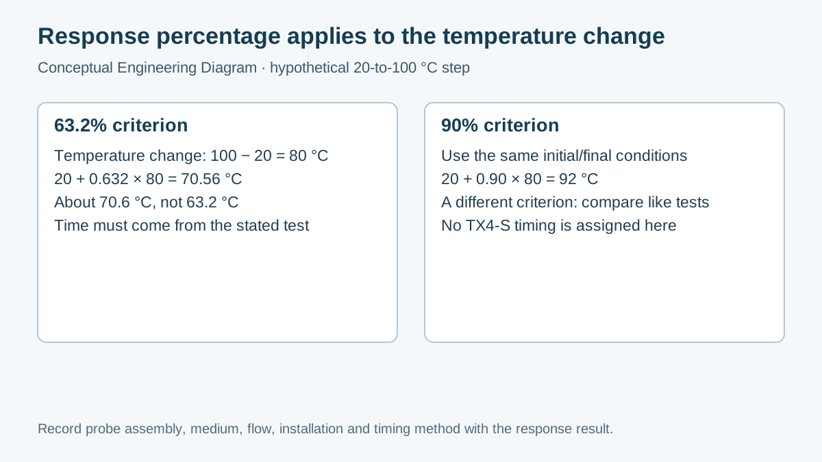
Assume a hypothetical sensor is exposed to a temperature step from 20 °C to 100 °C under a specified laboratory method. The size of that step is 100 − 20 = 80 °C. The 63.2% criterion is referenced to the change, not to the final temperature alone.
The corresponding temperature is 20 + 0.632 × 80 = 70.56 °C, or about 70.6 °C. A hypothetical trace reaching 70.6 °C after 4 seconds would have a 4-second 63.2% response under that test. It would not mean that the sensor reaches 100 °C in 4 seconds.
For comparison, the 90% criterion for the same step is 20 + 0.90 × 80 = 92 °C. The time at which the trace reaches 92 °C must be read from the trace or calculated from a justified model. Do not treat 4 seconds at 63.2% as 4 seconds at 90%.
| Criterion | Calculation | อุณหภูมิ |
|---|---|---|
| Initial condition | Defined starting value | 20 °C |
| Step size | 100 − 20 | 80 °C change |
| 63.2% of the change | 20 + 0.632 × 80 | 70.56 °C |
| 90% of the change | 20 + 0.90 × 80 | 92 °C |
| Final condition | Defined final value | 100 °C |
This arithmetic only establishes temperatures corresponding to the stated criteria. Real assemblies may have several thermal paths, nonuniform contact and more than one apparent time constant. It does not establish a first-order model, a TX4-S sampling period or a finished machine's protective response.
Which Delays Belong to the Measurement Chain?
Start with the physical process. The heat source and the product may change at different times and positions. A reference probe at one point cannot automatically define the exact temperature history at another point. State the measurand and the physical location before comparing traces.
Next consider the installed probe. Its geometry, contact, insertion, protective parts and surrounding flow govern how it exchanges heat with the process. Follow the sensor manufacturer's mounting instructions and retain the assembly description. Do not use a guessed universal immersion depth or a photograph-derived dimension as an acceptance rule.
Then record the configured controller input and any relevant processing settings documented for the supplied unit. Use the TX4 series instruction manual with the actual order code. Do not assume that a parameter exists or has a particular value merely because another controller offers it.
Finally, identify how the observations were collected. A human reading a display every 10 seconds, a video recording and an independent data logger create different timing records. The logging interval is not necessarily the controller's input-conversion interval. Preserve both when known, and state which timing uncertainty affects the result.
How Should an OEM Compare Two Probe Assemblies?
- Specify the process point, temperature transition, response criterion and allowed operating conditions. Decide whether the test assesses the probe, the complete input chain or the full machine.
- Identify both probes by full part number, sensing type, sheath and protective assembly. Confirm compatibility with the actual TX4-S input configuration.
- Keep the installation and test environment comparable. Record mounting, medium, flow and reference placement instead of relying on a shared nominal temperature.
- Use suitable synchronized recording equipment. Record the transition start and the criterion-crossing time, including observation and reference limitations.
- Compare results only within the defined method. Keep raw traces and note whether the final state was sufficiently established for the chosen criterion.
- Recheck the machine after an approved change. A faster probe can change control-loop behavior, noise susceptibility or the process relationship; it is not automatically a drop-in improvement.
Work on electrical connections, hot processes or moving equipment requires the machine's approved procedures and qualified personnel. Do not create an improvised temperature step that exceeds probe or equipment limits. Maintain any independent protective system while ordinary control performance is evaluated.
What Decision Should the Comparison Support?
Use the record to choose the next investigation, not simply to label one component “slow.” If the installed probe is the limiting thermal element, review its assembly with the probe supplier. If two suitable probes show similar physical behavior but the recorded indication differs, investigate configuration and observation timing with the controller documentation.
Preserve functional tradeoffs. Changing a grounded junction to improve thermal response can affect electrical isolation; reducing protection can affect mechanical or environmental suitability. Those issues require separate evidence. A shorter measured response under one method does not prove that the alternative is suitable for the complete application.
For a TX4-S input-chain review, send WEHO the order code, configured input, probe specification, installed assembly description and response record. Include the percentage criterion and test conditions. This gives the supplier a defined question and avoids requesting a generic “fast sensor” without a process requirement.
Engineering FAQ
Is a display refresh time the same as probe response time?
No. Display timing describes an electronic or presentation stage; probe response describes thermal behavior under stated conditions. A complete observation can include both, so identify the stage being measured.
Is 63.2% calculated from zero degrees?
No. Apply the percentage to the temperature change and add the initial value. For the hypothetical 20-to-100 °C step, the 63.2% criterion is 70.56 °C.
Can an air-test response be compared with a water-test response?
Not as a like-for-like result. The surrounding medium and its movement affect heat transfer. Request comparable methods or assess each assembly under the conditions relevant to the process.
Will a faster probe always improve a TX4-S loop?
No. The changed assembly can affect other thermal and electrical behavior. Verify compatibility and repeat the relevant machine acceptance tests after an authorized change.
Does this article specify a TX4-S response-time limit?
No. It explains how to define and compare a measurement method. Any controller-specific timing claim must come from the applicable WEHO documentation for the supplied configuration.