ESD testing for powered equipment evaluates how the complete product behaves when subjected to the specified electrostatic-discharge exposure. For an OEM, the release decision should use a documented point map, the required operating modes, and observations of power delivery, resets, communications, and application state.
A product that turns on after the test has not necessarily maintained its required function during it. Define acceptable behavior in advance, then link each result to the tested configuration and discharge point. This is particularly important when a supply continues delivering power while a controller or interface malfunctions.
Article sections
Keep equipment immunity separate from component ESD ratings
A semiconductor’s human-body-model (HBM) or charged-device-model (CDM) rating does not establish immunity of an assembled product. Texas Instruments explains this distinction: device ratings address handling or manufacturing stresses, while the system-level transient standards address a different evaluation. Do not treat matching kilovolt numbers from different tests as equivalent evidence.
IEC 61000-4-2:2025, edition 3, is a basic EMC reference for equipment exposed to electrostatic discharges, including discharges to nearby objects. Its scope excludes device sensitivity during handling and packaging. The IEC catalogue also states that product committees select the appropriate tests and severity for their equipment.
Record the edition adopted by the applicable product requirement or contract. A newly published basic standard does not by itself tell an OEM which edition its existing project must use. Resolve that question with the responsible compliance engineer and test laboratory before comparing reports.
Define the product boundary and accessible-point map
Describe the actual assembly: enclosure and finish, accessible metal parts, controls, displays, connectors, power supply, cable assemblies, grounding arrangement, and firmware. Attach photographs with stable point identifiers, so a later reviewer can tell where the exposure occurred.
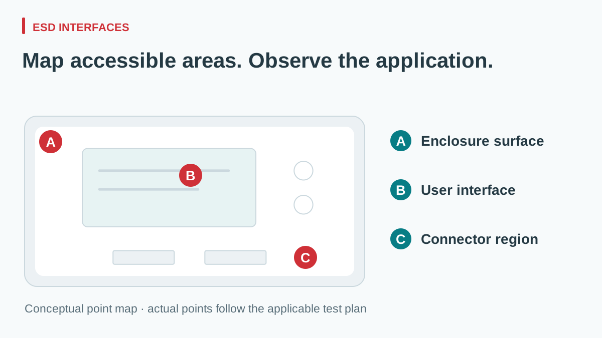
The point map should follow the applicable method and intended use. Record which configurations are relevant when a connector is mated, covered, or accessible during normal operation. Do not assume every internal pin must be exposed, or remove normal protection simply to create a convenient test point.
| Candidate area for assessment | Configuration to describe | Observation to associate with its point ID |
|---|---|---|
| Accessible chassis, seam, or fastener | Finish, bonding, normal enclosure assembly, and intended accessibility | Controller state, power behavior, and unintended outputs |
| User control or display area | Active screen, operating task, and normal user interaction | Touch/key response, display integrity, and application continuity |
| External connector or cable entry | Mated state, shield termination, cable, and applicable accessible surfaces | Communication integrity, port function, and reset events |
| Indirect-discharge arrangement where applicable | Laboratory setup and its reference in the test plan | Whole-equipment functional response linked to that test step |
View full diagram ↗
This is a planning matrix, not a list of mandatory points for every product. The laboratory should define the required direct or indirect exposure, contact or air-discharge method, polarity, levels, counts, and sequence from the applicable requirements. Retain that definition with the report rather than reconstructing it afterward.
Retain LRS-350-24 identity with the enclosure point map
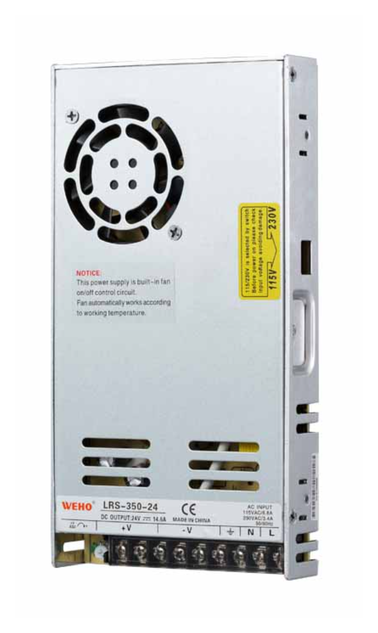
For an OEM enclosure using the WEHO LRS-350-24 enclosed AC-DC supply, link its exact model and revision to the equipment configuration record and LRS-350 public specification. Include the supply’s FG bond, mounting contacts, and harness routing in the review of possible paths from exposed enclosure or connector regions to internal circuits. Keep installed-layout and bonding photographs with the external point map. Their actual influence on a rail or controller must be evaluated in that configuration.
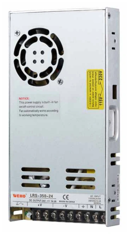
LRS-350-24 hardware reference; accessible ESD points belong to the equipment test plan.
View original photograph ↗
TI’s ESD Protection Layout Guide explains how the current return path and coupling to nearby circuits affect the voltage reaching protected electronics. That general mechanism supports documenting the installation; its PCB examples do not define the bonding arrangement for this WEHO supply. Request any available supply-level ESD evidence with its scope, then agree complete-equipment coverage with the laboratory. Internal terminals are not automatically accessible discharge points, and no ESD result for LRS-350-24 is asserted here.
Monitor the application, not just the supply indicator
Choose operating tasks that exercise the interface associated with each point-map ID. For a display or user control, record the active screen, the command being entered, and the expected response. For a connector region, retain the mated state and representative traffic. Tie observations to the plan-assigned contact, air, or indirect-discharge method and the exact test step; do not substitute a successful final screen refresh for an intact command or transaction.
For a power-related fault, monitor the relevant rail at the sensitive load as well as the supply output where appropriate. Record reset causes and application events alongside electrical observations. A controller restart can have several possible paths; it should not automatically be attributed to loss of the main supply.
| ESD evidence | What to associate with the point ID | Acceptance question |
|---|---|---|
| Discharge step and enclosure state | Point photograph, plan-assigned method, polarity, step identifier, and normal cover or connector state | Can the observed behavior be tied to the actual exposure location and configuration? |
| User-interface task | Active screen, key or touch interaction where fitted, command in progress, and visible recovery | Did the interface complete the intended action without an unintended output? |
| Reset and rail correlation | Reset count and cause, firmware, retained state, monitored rail location, and common time reference | Was there a restart, a captured rail disturbance, or a display-only symptom? |
| Transaction and stored-state integrity | Request and acknowledgment IDs, missing exchanges, settings, counters, alarms, and post-step function check | Did the required exchange and state survive, rather than merely the display returning? |
Define the normal state and allowed behavior for each channel before exposure. Where the governing requirements permit a temporary disturbance, specify the relevant recovery and state-integrity conditions. Where uninterrupted performance is required, automatic recovery does not make an interruption disappear from the assessment.
Document monitoring limitations. An event log may not capture a short rail excursion, and a voltage trace may not reveal an incorrect application state. Have the laboratory review probes and monitoring connections so the observation arrangement is identified and does not silently change the equipment configuration.
Example: the display recovers but a transaction is lost
Consider a hypothetical OEM controller with an enclosed supply, a display, and an external communication port. During an ESD exposure at a front-panel point identified as P03 in the agreed point map, the display freezes briefly and then returns. The supply’s status indicator remains on. The application log shows that one transaction did not complete.
The release decision depends on the pre-agreed functional requirement. If that transaction had to complete without interruption, visual recovery is insufficient. Preserve the point-map photograph, exact point ID, relevant connector or cover state, test step, operating mode, logs, and equipment configuration. If the monitoring cannot establish whether a rail excursion occurred, record that uncertainty instead of declaring that the supply was unaffected.
After corrective work, identify the changed hardware, cable, bonding, or firmware and determine the required repeat evaluation. Keep the original finding and the revised result together. A favorable repeat at one point does not erase other applicable points or operating modes from the plan.
Keep ESD, EFT, and ordinary power checks distinct
ESD and electrical fast-transient/burst testing apply different disturbance methods. For planning repetitive bursts at supply and signal/control ports, use the EFT test planning and system-evidence guide. An ESD point-map record and an EFT port record answer different exposure questions; a pass in one is not a substitute for the other. Acceptable steady-state output voltage or ripple also does not establish transient immunity of the complete equipment.
Use the ripple acceptance guide to organize baseline electrical measurements, with their own conditions. When changing the power supply or its installation, the power-supply replacement checklist helps identify which interfaces and evidence need review.
Request a report that can support the next build
A useful ESD report ties results to the model and revisions, photographs and point map, cables and enclosure, operating modes, adopted method, equipment validity, observations, and performance criteria. It should identify anomalies, interventions, changes, and the final disposition.
Ask the supplier which evidence covers its power-supply assembly and what conditions apply. Keep that scope separate from the OEM’s complete-product evaluation. Store the qualified configuration with the purchasing record so later substitutions receive an informed change review.
Send WEHO your proposed power-supply configuration and equipment-validation requirements, including the enclosure, relevant interfaces, load, adopted standard references, and required behavior. Ask what model-specific documentation is available before deciding how it will contribute to your equipment-level ESD evidence.