A power supply startup time is useful only when its start and finish events are defined. An input-to-output delay, a voltage rise interval and a machine-ready time answer different questions. For an OEM integrating a controller, the practical decision is whether the complete power-up sequence meets the equipment deadline under the specified conditions.
On this page
Write that deadline before comparing milliseconds. A supply that raises its output quickly after a long delay may still miss it. A rail that crosses its nominal voltage once may also be too early for the controller to begin reliable operation.
Choose the event that your equipment actually needs
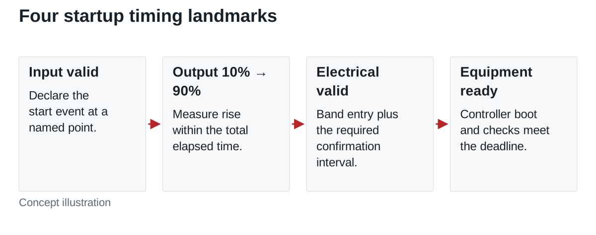
Define the input event at a named measurement point. Depending on the design, this could be AC becoming valid at the supply input, a DC bus crossing a specified threshold, or an enable command becoming valid. These events are not interchangeable. Measuring from an enable signal excludes any delay before that signal; measuring from a switch command can include upstream switching and bus behavior.
Then define output landmarks. TDK-Lambda’s explanation of output rise and fall characteristics distinguishes the delay before output establishment from the rise itself. Manufacturers can use different thresholds and terms, so copy the definition accompanying the timing value rather than assuming that every “startup time” uses the same endpoints.
| Timing item | Example boundary to specify | Decision it supports |
|---|---|---|
| Setup delay | Input valid to output crossing 10% of the target | How long before appreciable output appears? |
| Voltage rise | Output crossing 10% to crossing 90% | How quickly does the rail make this part of its transition? |
| Electrical validity | Input valid to output entering the agreed band and remaining there for the required interval | When can the rail satisfy its load? |
| Equipment readiness | Input valid to the controller completing its own boot and checks | When can the equipment perform its intended function? |
The 10% and 90% thresholds above are an example convention for a test specification. Use the actual supplier definition when interpreting a datasheet. For a nominal 24 V rail, those example crossings are 2.4 V and 21.6 V; neither is automatically the controller’s valid operating threshold.
Turn a timing trace into a deadline calculation
Consider this hypothetical 24 V controller installation. Time zero is the documented input-valid event at the supply terminals. The output reaches 10% at 180 ms and 90% at 205 ms. It enters the equipment’s agreed voltage band at 220 ms and remains within that band for a required 10 ms confirmation interval. In this example, the output must remain in the band continuously for the 10 ms confirmation interval; an excursion restarts that interval.
The setup delay is 180 ms under these declared definitions. The 10–90% rise time is 205 − 180 = 25 ms. The electrical-valid declaration occurs at 230 ms, after the confirmation interval. If the controller then needs 80 ms to complete boot and checks, the equipment becomes ready at 310 ms. Against a 350 ms deadline, the example has 40 ms of margin.
Do not add the 25 ms rise time to the 230 ms declaration time: the declaration already includes the preceding rise. Also avoid treating the 40 ms as guaranteed production margin. These are invented values illustrating the calculation, not measurements of a WEHO supply or a recommended controller threshold.
If the controller starts booting before the validity declaration, its timing may overlap instead of adding sequentially. Capture that behavior explicitly. A calculation that assumes sequential stages cannot establish the readiness of an overlapping sequence.
Make supplier timing values comparable
A procurement table should retain the test conditions beside every timing number. Record the input voltage and frequency where applicable, the load at startup, connected output capacitance, ambient or relevant component temperature, and the state before power-up. Keep typical and maximum values separate. A typical value from one condition cannot establish compliance with a maximum equipment deadline.
Ask whether the specification describes a fully discharged start, an enable-controlled restart, or another state. An input interruption that leaves internal or external energy stored can produce a different sequence. The start event and output landmarks should be the same for each comparison, or the differences must be identified before ranking candidates.
Do not substitute hold-up time for startup time. Hold-up describes the continuation of output after an input interruption under stated conditions. If a datasheet combines several timing labels in one row and the value-to-label mapping is unclear, request clarification rather than assigning the numbers by position.
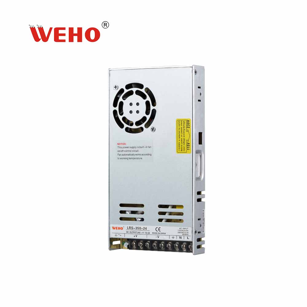
For an actual candidate such as the WEHO LRS-350-24, attach the LRS-350 specification to the timing request. Its public sheet combines setup, rise and hold-up labels in one timing row; confirm which values and conditions apply before placing them in the equipment budget. The timing example above remains hypothetical.

Verify the sequence in the equipment
Qualified personnel should define the measurement arrangement and equipment appropriate to the electrical environment. For the timing record, capture the input-valid event, output voltage and any power-good or controller-ready signal used by the design on a common time reference. Specify the threshold, bandwidth and any filtering or debounce that changes when an event is declared.
Include the load sequence that will actually occur. A controller may start alone and then enable other circuits. An output that initially rises into range can leave it when the next load starts, so the acceptance rule must cover the required interval through that event. Whether a capacitive load can start successfully is a separate qualification question; include that load state in the timing plan when it applies.
Repeat the relevant input, temperature, load and restart conditions from the equipment specification. Save both representative traces and the slowest observed compliant sequence, together with the number of trials. Repeated observations help evaluate consistency; they do not replace a supplier’s stated worst-case limits.
Approve the complete timing budget
Approve a candidate when its documented boundaries are understood and the equipment sequence meets the agreed deadline across the required conditions. Hold the decision when a timing value lacks a definition or a required corner remains untested. Revise the architecture or candidate when the valid-output and controller-ready sequence exceeds the deadline.
The handoff to purchasing should name the supply model and document revision, timing definitions, required conditions, deadline and evidence supporting the decision. This makes “fast startup” a requirement that engineering and a supplier can discuss precisely.
Send WEHO your output requirement, input-valid definition, load sequence and equipment-ready deadline so the relevant model documentation and validation questions can be reviewed.