An external LC filter can reduce differential-mode switching ripple at a load, but the added network must be checked with the power supply and load together. Confirm that the exact supply permits the proposed output network and feedback connection. Then compare startup, load-step behavior and ripple at both the supply terminals and the load. A cleaner steady-state waveform alone is insufficient to accept the change.
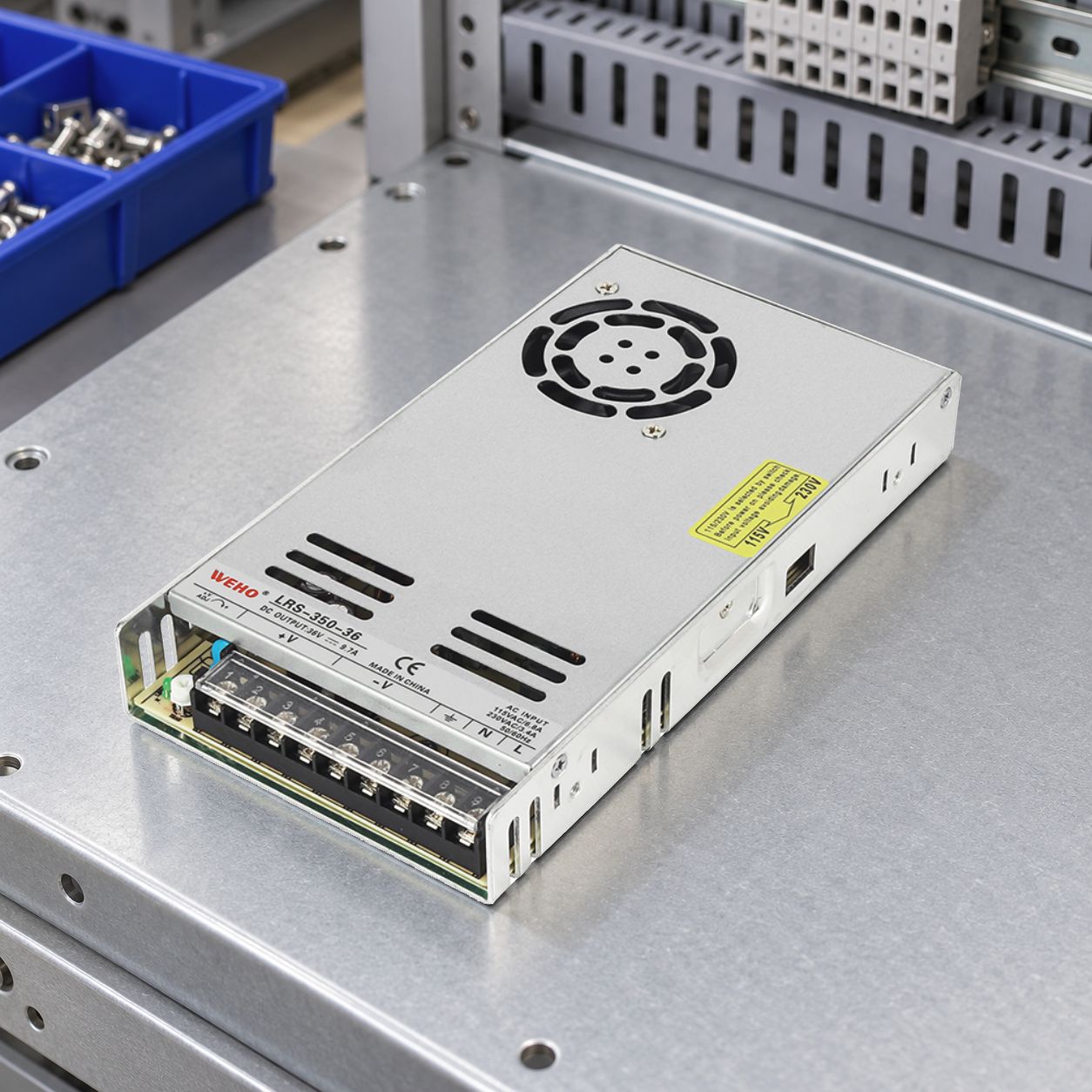
This guide is for OEM engineers considering a filter on the DC output of a finished switching power supply. It provides a review and test method, rather than a universal set of component values. Board-level converter examples illustrate the principles; they do not establish compatibility with a particular WEHO model.
1. Define the problem at the load
Write the requirement before selecting an inductor: the load’s allowed DC voltage range, ripple limit and measurement bandwidth, load-current range, and permitted excursions during startup and load changes. Record the cable length and the load’s own input capacitance.
These details determine what “better” means. A filter that lowers switching ripple but creates an unacceptable voltage dip when the load turns on has not solved the equipment requirement. If the existing measurement is uncertain, first establish a repeatable method using power-supply ripple acceptance criteria.
Keep the scope clear: this is an output network between the SMPS and its load. A DC-DC converter’s input-filter interaction is a different problem, covered in DC-DC input-filter resonance and source impedance.
2. Check where the supply senses voltage
In Figure 1, point A is at the supply terminals and point B is at the load. Record where the regulator’s feedback actually measures voltage; do not assume it is at B simply because the load is connected there.
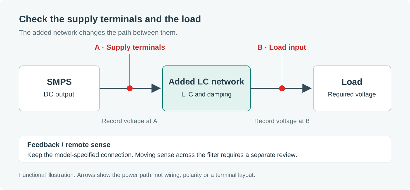
If the supply regulates at A, the series path can introduce a voltage difference at B. Remote sensing at B may compensate for some DC drop when the manufacturer permits that arrangement, but including the added filter in the sensed path also changes the control problem. Moving sense wires is not a general remedy for ringing.
Analog Devices’ second-stage output-filter design discussion examines the effects of filtering and feedback placement. Its examples also show why a filter outside the feedback path should not automatically be treated as dynamically harmless.
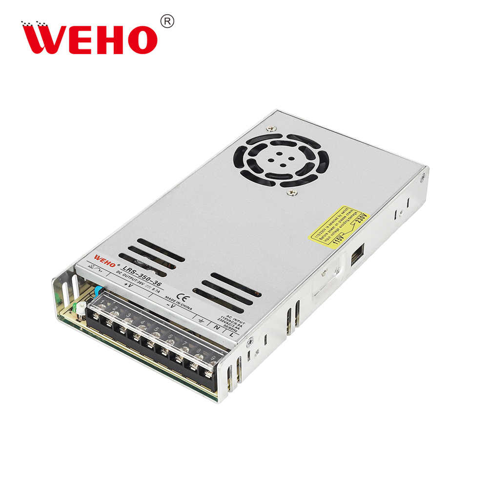
For a finished supply, obtain the model-specific limits for external capacitance, remote-sense compensation and any allowed post-filter arrangement. If the internal control-loop details are unavailable, retain the documented sense connection and ask the manufacturer to review the proposed network. Do not infer an approved configuration from a different converter’s application circuit.
3. Review the complete output network
An LC label does not describe every relevant property. Review the parts as they will operate, including temperature, bias and the load already connected.
On small screens, scroll sideways to compare the network requirements.
| item | What to establish | Why it changes the decision |
|---|---|---|
| Series inductor | Inductance versus current, saturation rating, thermal current rating and DC resistance. | Inductance and heating need separate checks at the relevant current. |
| Added capacitor | Effective capacitance, ESR, ripple-current capability, voltage and temperature limits. | The operating values, rather than the label alone, define the network. |
| Damping | Documented damping method and its losses over the operating range. | A low-loss LC network can have a pronounced resonance peak. |
| Load and interconnect | Load input capacitance, cable resistance/inductance, startup sequence and current transitions. | The installed system differs from an isolated filter calculation. |
Coilcraft distinguishes saturation current and RMS current ratings: they describe different constraints. Passing one rating does not establish the other.
Texas Instruments’ second-stage filter design article explains the importance of damping and the tradeoff with attenuation. Use that principle to request a justified design; its particular component ratios and damping values are not general rules for enclosed industrial supplies.
If a ferrite bead is proposed instead of an inductor, review its impedance versus frequency and DC bias. Do not substitute a bead’s single advertised impedance value into a constant-inductance LC calculation. Analog Devices discusses these effects in Ferrite Beads Demystified.
4. Calculate resonance and DC loss separately
The following numbers are an illustrative calculation, not a filter recommendation or a WEHO test result. Assume an ideal inductance of 10 µH, an effective capacitance of 47 µF, a 5 A steady load, and a series-inductor DC resistance of 40 mΩ at the evaluated condition.
Ideal LC natural frequencyf₀ = 1 / (2π√LC) ≈ 7.34 kHz
Inductor DC voltage dropΔV = I × R = 5 A × 0.040 Ω = 0.20 V
Inductor resistive dissipationP = I²R = (5 A)² × 0.040 Ω = 1.00 W
The natural frequency is not a measured oscillation frequency or a universal −3 dB cutoff. Damping changes the peak and shape of the response. The resistance calculation accounts only for the stated inductor resistance; connectors and cable add their own losses, and it does not predict temperature rise.
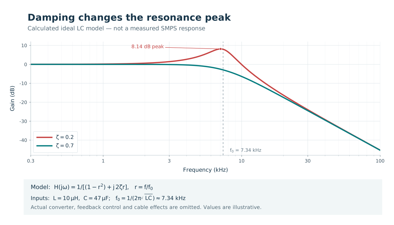
The plotted model is H(jω) = 1 / [(1 − r²) + j2ζr], where r = f/f₀. The damping ratios ζ = 0.2 and 0.7 are independently chosen examples; L and C alone do not determine them.
The useful next question is whether the load still receives an acceptable voltage during its actual current transitions. Neither the nominal LC frequency nor a steady-load ripple reading answers that question.
5. Use a before-and-after acceptance matrix
When load current rises abruptly, current through the series inductor cannot change instantaneously. The load-side capacitor supplies the initial current mismatch, while the voltage response depends on the supply, filter and load together. This is why the load’s transition profile matters as much as its steady current.
Keep the supply, input conditions, load program, wiring and measurement method consistent when comparing the original and filtered configurations. Capture A and B during the same event where practical, with probes and instruments appropriate to the circuit’s isolation and voltage. Do not connect an earth-referenced instrument in a way that changes the intended reference.
Fill in the project’s numerical limits before testing. The table below is a proposed engineering record, not a claim that any model has passed these checks.
On small screens, scroll sideways to compare each check with its acceptance basis.
| Check | Record before and after adding the filter | Acceptance basis |
|---|---|---|
| Steady load | Voltage at A and B; ripple at the agreed bandwidth and load points. | Supply-terminal limits at A; load DC and ripple limits at B, each with its agreed method. |
| Startup and restart | Rise, overshoot, startup time and any repeated restart or protection event. | Load startup requirements and the supply’s permitted output network. |
| Load increase | Current-step endpoints, edge rate, minimum voltage and recovery at B; compare A. | Load undervoltage tolerance, recovery requirement and functional behavior. |
| Load decrease | Maximum voltage, ringing and recovery at B. | Load overvoltage tolerance and recovery requirement. |
| Light-load modes | Behavior at the lowest intended load and relevant operating-mode transitions. | Required voltage/ripple range and absence of unacceptable functional disturbance. |
| Operating corners | Repeat critical events at specified input and temperature limits. | The project envelope and component operating limits. |
| Thermal and functional run | Inductor temperature, voltage drop, component stress and actual equipment operation. | Part ratings and equipment acceptance criteria. |
Added capacitance must charge during startup. TI’s discussion of startup into heavy capacitive loads shows that current limit and soft-start behavior can affect successful startup. The relevant limit belongs to the actual supply and operating condition, not to a universal capacitance allowance.
A successful set of load steps gives useful evidence within the tested envelope. It does not, by itself, establish control-loop margins across every condition. Where loop-interaction risk remains unresolved, request the manufacturer’s analysis or an appropriately qualified stability assessment.
6. Decide what can be released
Record the result against the exact configuration: supply model and revision, filter parts, damping, sense connection, cable, load settings and test conditions. Keep both the ripple improvement and the worst observed startup or load-step behavior in the decision record.
If ripple improves but load voltage exceeds its permitted range, revise the network or reconsider the power architecture. If the result depends on an undocumented sense connection or unknown component limits, resolve those gaps before treating the combination as qualified. When a configuration meets the agreed requirements, preserve its parts and conditions so later substitutions can be reviewed against the same evidence.