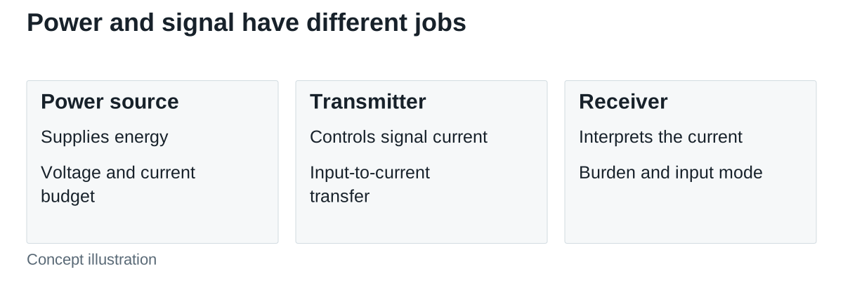
A 24 V power supply does not become a 4–20 mA signal converter because a sensor uses both numbers. The supply provides energy; a transmitter or interface regulates signal current; the receiver interprets it. Before selecting OEM power hardware, identify which device powers the loop, which controls current and what voltage remains available at the worst operating point.
On this page
This distinction prevents an equipment team from ordering the wrong function. It does not imply that WEHO supplies a signal converter or that any nominal 24 V model is suitable for a particular instrumentation loop.
Identify the function behind the search term
A request for a “24V to 4–20mA converter” can mean a powered voltage-to-current interface, a sensor transmitter, an isolated conditioner or simply a supply for an existing loop. Start with the source signal and destination input. State whether the information originates as a sensor measurement, analog voltage or another current signal.
A regulated 24 V source has a voltage output and a current capacity. A 4–20 mA transmitter deliberately changes current to represent information. The supply’s available ampere rating is not the loop’s command scale, and connecting an ordinary voltage source does not provide the missing conversion function.
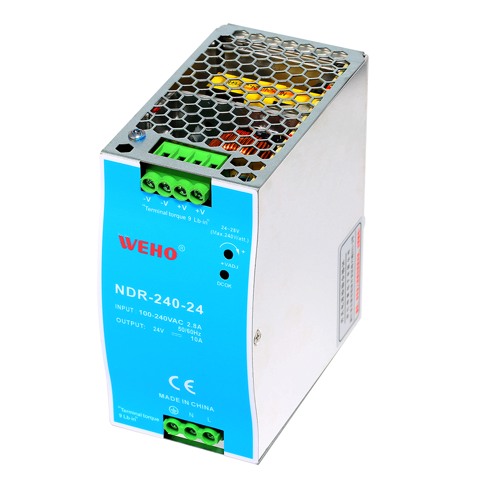
For example, WEHO NDR-240-24 product information identifies a 24 V DC output supply. Review its model specification as the energy-source candidate, then verify available terminal voltage and the actual loop requirements. That role does not turn the NDR-240-24 into a transmitter or a voltage-to-4–20 mA signal converter. Keep the signal-conversion device and its compliance requirements as separate line items.

Resolve active and passive at each interface
TI’s current-loop transmitter configuration lesson distinguishes two-, three- and four-wire arrangements. A two-wire loop-powered transmitter obtains power from the loop while controlling its current. Other arrangements use separate power connections. The wire count and exact terminal functions must come from the device instructions.
“Active” and “passive” are useful labels only when their meaning is stated. One vendor may describe whether an output sources loop energy; another may describe a receiver that includes a loop supply. Draw a functional responsibility map and identify the power-providing element. Do not combine two powered interfaces or assume that two unpowered interfaces can operate together.
| İşlev | Evidence to request | Question that must be answered |
|---|---|---|
| 24 V source | Output tolerance, load range, ripple, startup and protection behavior | Can it maintain the required loop voltage in all defined states? |
| Transmitter or converter | Power method, input signal, output span and minimum operating voltage | What regulates the signal current, and under what load? |
| Receiver | Input mode, burden and common-mode limits | Does it provide loop power or only measure current? |
| Other series elements | Cable resistance and applicable isolator, barrier or protection drops | How much compliance voltage remains at maximum required current? |
Keep functional isolation separate from the supply’s insulation specification. An AC-DC supply’s isolation does not automatically isolate one analog channel from another. Likewise, an isolated signal conditioner does not establish the complete equipment’s protective or grounding arrangement.
Calculate the loop’s voltage reserve
TI’s two-wire transmitter explanation shows that excessive series voltage drop can leave a transmitter below its minimum operating voltage and prevent current regulation. Its XTR116 circuit is a particular example; use the actual transmitter’s limit rather than transferring that device’s voltage requirement.
A useful budget is: minimum available supply voltage minus the transmitter’s required voltage, minus receiver, cable and other series drops. Use the maximum current that must remain valid, including any required diagnostic current. Account for non-resistive drops separately rather than representing every element with an assumed resistance.
Worked example with explicit assumptions
Assume a nominal 24 V source can be as low as 21.6 V under the conditions being assessed. A hypothetical transmitter requires at least 9 V. The receiver burden is 250 Ω, and the combined round-trip cable and other modeled resistance is 100 Ω. Evaluate the required 20 mA endpoint.
Total modeled resistance is 350 Ω, giving a 0.020 A × 350 Ω = 7.0 V drop. The reserve is 21.6 − 9 − 7 = 5.6 V. At 4 mA, those resistances drop 1.4 V. These figures are arithmetic examples, not specifications for a transmitter, safety barrier or WEHO supply.
If an added device requires a further 6 V at 20 mA, the calculated reserve becomes −0.4 V. The endpoint is no longer covered by the stated assumptions. A positive reserve is also not a universal pass margin: measurement uncertainty, tolerance, temperature and additional transient requirements must fit within the project’s own allowance.
This calculation addresses available loop voltage. The supply’s total current budget is a separate exercise covering all loops, interface electronics and credible startup or fault demand. Multiplying one channel’s normal 20 mA by a channel count may omit other powered circuitry.
Qualify readings as well as power
Agree the signal error, permitted ripple, settling and behavior on open circuit or loss of supply. Test the required current endpoints and intermediate values with the actual receiver burden and representative cable conditions. Record voltage across the transmitter and the indicated value at the receiver, not just the supply’s unloaded output.
Include the sequence in which the supply, transmitter and receiver become ready. A supply that eventually reaches 24 V does not establish the validity of every reading during startup. Where the process uses fault currents outside the normal span, confirm which interface generates them and how the receiver identifies them.
Carry out measurements through the device manufacturers’ permitted methods. A powered loop is not an invitation to experiment with unknown terminal combinations. The acceptance record should identify the instrument setup and reference connections so the measurement does not silently change the loop configuration.
Give the supply supplier a power requirement
Send WEHO the proposed model, loop count, minimum acceptable voltage at the powered devices, total current schedule and relevant ripple or startup limits. Attach the transmitter, converter and receiver interface requirements. Ask for a model-specific power-source review while keeping signal conversion and channel-isolation approval with their responsible suppliers.