



Key Engineering Takeaways
- An LDO can reduce conducted supply noise only within its documented operating conditions.
- Calculate minimum input voltage at the LDO pins, including ripple and transient dips.
- Check maximum input voltage and dissipation separately from the dropout calculation.
- Verify noise rejection at the relevant frequency, load, headroom, and capacitor configuration.
Select a post-regulator for the sensitive rail
Adding a low-dropout linear regulator (LDO) after a switching supply can improve a sensitive rail, but a nominal voltage difference is insufficient evidence. The LDO can lose regulation during a brief input dip or overheat at the opposite voltage extreme. Noise performance must be assessed at both the required operating point and the frequencies that affect the load.
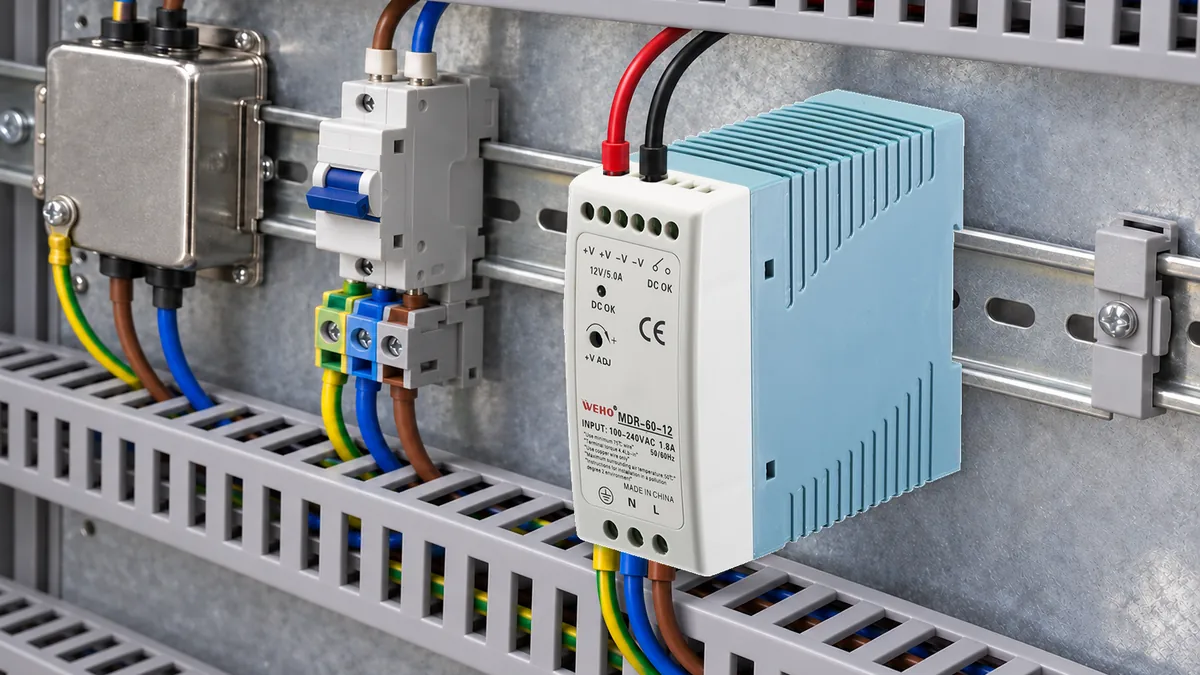
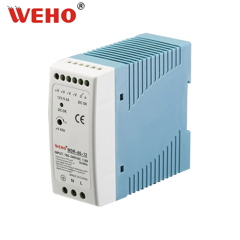
The WEHO MDR-60-12 DIN-rail supply is a 12 V, 5 A supply variant. In a possible system architecture, an independently selected DC-DC stage could reduce that upstream rail before an LDO supplies a low-voltage analog circuit. The buck converter and LDO discussed below are separate design elements, not stated features of the MDR-60-12.
This task differs from deciding between linear and switching conversion. WEHO’s linear regulator versus buck comparison addresses that earlier choice. Here, the decision is whether an LDO post-regulator has a workable voltage and thermal window after the switching stage has already been selected.
Build a minimum and maximum voltage window
Headroom is the voltage available between the LDO input and output. Dropout is the limit below which the LDO cannot maintain the intended regulation. An LDO can require more headroom for a specified power-supply rejection ratio (PSRR) than it needs merely to avoid dropout. Analog Devices explains this distinction in its LDO concepts tutorial.
Calculate minimum input at the LDO pins rather than assuming the switching regulator setpoint reaches them unchanged. Include the applicable output tolerance, wiring or filter drop, ripple valley, and transient dip. Combine limits conservatively when they can coincide; where they cannot, document the operating cases instead of adding unrelated worst cases without explanation.
For the low-voltage check, compare that minimum with the highest allowed LDO output plus its required dropout or noise-performance headroom at the relevant current and temperature. Use the exact LDO datasheet conditions. A typical dropout curve cannot automatically replace a guaranteed maximum needed by the project.
The upper-voltage check is different. Include high source tolerance, ripple peak, startup overshoot, and any credible fault or sequencing condition. Compare against the LDO’s recommended operating limits and evaluate abnormal conditions against the applicable absolute limits. An absolute maximum rating is a damage boundary, not a continuous operating target.
Work through a hypothetical 5 V rail
The following calculation is a hypothetical design exercise, not a test of a WEHO supply or a particular LDO. Assume a 5.00 V output with ±1% total tolerance, a maximum 0.80 A load, and an external buck regulator initially set to 5.60 V with ±3% combined tolerance.
Also assume a 0.10 V distribution drop, a 0.06 V ripple valley, and a 0.15 V load-step dip that can coincide. The candidate LDO requires at most 0.25 V dropout under the stated load and temperature conditions. Its hypothetical noise requirement needs at least 0.40 V headroom at the same operating point.
The initial minimum input is:
Vin,min = 5.60 × 0.97 − 0.10 − 0.06 − 0.15 = 5.122 V.
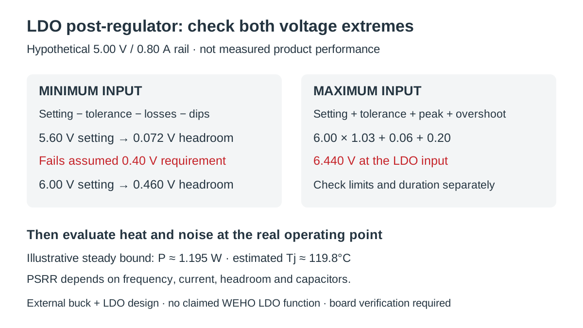
The maximum output is 5.00 × 1.01 = 5.050 V. Available worst-case headroom is therefore 5.122 − 5.050 = 0.072 V. The proposed setting fails both the assumed 0.25 V regulation requirement and the 0.40 V noise headroom requirement.
Swipe horizontally on a small screen, or open the full-size diagram.
Raising the buck setpoint to 6.00 V gives Vin,min = 6.00 × 0.97 − 0.10 − 0.06 − 0.15 = 5.510 V. The resulting 0.460 V headroom clears both assumed thresholds. That result justifies continuing the evaluation; it does not complete the input-voltage, noise, thermal, or startup checks.
| Low-voltage check | 5.60 V setting | 6.00 V setting | Meaning |
|---|---|---|---|
| Minimum LDO input | 5.122 V | 5.510 V | Includes the listed coincident deductions. |
| Maximum LDO output | 5.050 V | 5.050 V | Same assumed output tolerance. |
| Available headroom | 0.072 V | 0.460 V | Compare at the required load and temperature. |
| Assumed 0.40 V noise requirement | Not met | Met in calculation | Confirm with the actual device and board. |
Recheck heat after increasing the setpoint
For the 6.00 V option, assume a 0.06 V ripple peak and a 0.20 V overshoot in addition to the high tolerance. Use no distribution drop for this conservative upper-bound case: Vin,max = 6.00 × 1.03 + 0.06 + 0.20 = 6.440 V. The actual candidate must permit that operating voltage and any separately evaluated abnormal transient.
Assume the upper bound can persist for the thermal screening exercise. At the minimum 4.950 V output, 0.80 A load, and 0.50 mA ground current, estimated dissipation is (6.440 − 4.950) × 0.80 + 6.440 × 0.00050 = 1.195 W, approximately 1.20 W. Ground current must be taken at the applicable operating point, not simply from the no-load quiescent-current headline.
Using a hypothetical 50°C/W junction-to-ambient thermal resistance and 60°C local ambient gives Tj ≈ 60 + 1.195 × 50 = 119.8°C. This is a screening estimate. Toshiba’s LDO thermal calculation guidance warns that thermal resistance depends on specified board conditions, so the real PCB requires evaluation.
A short overshoot does not have the same thermal effect as a sustained voltage increase. Record its duration and use an appropriate transient thermal assessment when the steady-state bound is unnecessarily conservative. Do not rely on thermal shutdown as the normal operating control or treat a case-temperature reading as a direct junction-temperature measurement.
Check rejection where the unwanted signal exists
PSRR is frequency dependent and varies with operating conditions. Analog Devices’ low-headroom analysis shows why reduced headroom can weaken rejection well before a design delivers the expected noise performance. Check the curve at the relevant output current and voltage difference, including switching-frequency components and significant harmonics.
For an illustrative single-frequency calculation, assume 20 mV peak-to-peak of input ripple and 40 dB PSRR at that frequency under the actual operating conditions. The estimated transmitted component is 20 mV ÷ 10^(40/20) = 0.20 mV peak-to-peak. This is only the input-ripple contribution; it is not the total output-noise specification.
An LDO also generates its own noise. Analog Devices’ AN-1120 distinguishes intrinsic regulator noise from externally applied supply noise. Do not add a broadband RMS noise figure directly to a peak-to-peak ripple number. Define bandwidth and measurement convention before combining contributions or comparing results with a sensitive load’s limit.
| Acceptance item | Evidence needed | What changes the decision |
|---|---|---|
| Düzenleme | Minimum input, maximum output, dropout limit | Coincident dips exhaust headroom. |
| Noise performance | PSRR curves and intrinsic-noise conditions | Required frequency or operating point differs. |
| Sıcaklık | Dissipation and board thermal evaluation | Higher ambient or less copper increases temperature. |
| Stable operation | Specified capacitance, ESR, layout, sequencing | Actual effective capacitance or supply order changes. |
Capacitors belong to the complete design. TI’s switcher-plus-LDO design brief identifies capacitor variation with voltage and temperature and the need to support both stages correctly. Follow the selected devices’ stability and layout requirements; adding an arbitrary filter can introduce another dynamic interaction.
Verify the complete rail
- Define the load limits. Record voltage accuracy, maximum current, load-step profile, acceptable noise bandwidth, and startup sequence. Verify that the limits come from the powered circuit’s requirements.
- Calculate both input extremes. Record tolerances and coincident events at the LDO pins. Verify low-side headroom and high-side operating limits separately, with the exact LDO data.
- Evaluate the thermal path. Record package, PCB copper, airflow, ambient, and dissipation cases. Check the assembled board under representative hot conditions using an appropriate junction-temperature assessment.
- Measure the intended noise quantities. Record probing arrangement, instrument bandwidth, load, source mode, and temperature. Compare like quantities against the stated load limits and check for measurement pickup.
- Exercise startup and transients. Record input/output waveforms, recovery, sequencing, and shutdown behavior. Verify the datasheet requirements for capacitance and any reverse-current or prebiased-output conditions.
Document the upstream supply interface
Use the MDR-60-12 product and ratings entry to identify the upstream supply, then send WEHO your DC interface requirements. Include the downstream converter input range, load profile, operating environment, and required source measurements. Qualify the separate buck/LDO design with its own component documentation and board evidence.
Engineering FAQ
Does an LDO always remove switching ripple?
No. Ripple rejection depends on frequency, headroom, load, and the complete implementation. Check the selected LDO’s curves and measure the required output quantity at the actual operating point.
Can I use the typical dropout value as the entire voltage margin?
Not when the design needs guaranteed regulation across its operating range. Use the applicable maximum dropout requirement and separately check the headroom needed for the desired noise performance.
Is raising the switching regulator voltage always better?
No. More input voltage may improve headroom but increases LDO dissipation and can violate its operating limits. Check the low-voltage and high-voltage cases together before changing the setpoint.
Does an LDO provide galvanic isolation from the upstream supply?
No. An ordinary LDO regulates voltage without creating a galvanic isolation barrier. Any required isolation must be provided and verified elsewhere in the power architecture.



