



- RTD insulation leakage can divert measuring current and reduce the resistance presented to a readout.
- A parallel-resistance example explains the error mechanism without predicting a particular installed fault.
- Keep probe insulation evidence separate from lead compensation, curve selection and controller insulation ratings.
- Approve the complete sensing arrangement using applicable probe tests and a documented temperature comparison.

Investigate a low reading before adding an offset
An RTD can produce a stable, plausible temperature while an unwanted leakage path biases its resistance measurement. A display correction can conceal that symptom at one point without identifying the damaged insulation or unsuitable installation. Establish the electrical path and probe condition before releasing a corrected production setting.
Le WEHO TX4-W temperature controller provides the receiving-instrument context for this investigation. The exact input configuration and probe still need their applicable documents. A front-panel photograph cannot establish the probe's insulation resistance, the leakage topology or the accuracy of an installed measurement.
Separate the probe's insulation from the controller's specification
An RTD readout is intended to determine the sensing element's resistance through its supported connection arrangement. An unwanted conductive path can allow some measuring current to bypass the intended resistance. The resulting error depends on where that path connects, not simply on whether a continuity buzzer sounds.
The BIPM's industrial platinum resistance thermometer guide, section 4.5 models insulation leakage as a resistance in parallel with the sensing resistance. That model lowers measured resistance and helps explain a low indicated temperature. It does not identify every possible conductor-to-sheath or conductor-to-earth circuit in an assembled machine.
Probe construction and condition matter to this assessment. Fluke's temperature-sensor calibration failure guide identifies low insulation resistance as a shunting mechanism and describes compromised seals, bent sheaths and moisture as possible contributors. Those are investigation leads rather than proof that a particular probe has failed in that way.
Keep a controller's own insulation specification in a different record. The WEHO TX4 manual includes instrument insulation information, but that is not a probe-insulation test instruction. It does not authorize applying an insulation tester through the controller's sensor input or borrowing an instrument test voltage for an attached probe.

Calculate a hypothetical parallel-path example
Assume an ideal Pt100 element is exactly at 100°C, with R₀ = 100 Ω and the positive-temperature reference coefficients A = 0.0039083/°C and B = −0.0000005775/°C². NI's RTD coefficient documentation lists this reference characteristic. The calculation assumes zero lead error, zero self-heating and an ideal readout using that same curve.
For temperatures at or above 0°C, use R(T) = 100 × (1 + A × T + B × T²). At 100°C, the resulting resistance is 138.5055 Ω. These ideal conditions isolate one error mechanism; they are not TX4-W or probe performance specifications.
Now introduce an assumed leakage resistance Rleak directly across the sensing element. The equivalent resistance is Rmeas = R × Rleak ÷ (R + Rleak). This is a deliberately simplified two-node parallel model, not a claim that every sheath-leakage arrangement has exactly the same connection.
With Rleak = 10,000 Ω, Rmeas = 138.5055 × 10,000 ÷ 10,138.5055 = 136.6133 Ω. Inverting the same Pt100 reference curve gives approximately 95.015°C. The modeled error is therefore 95.015 − 100 = −4.985°C, despite a perfectly stable true element temperature.
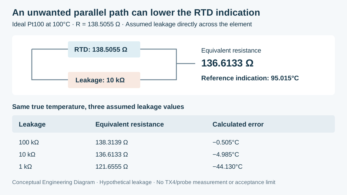
Swipe horizontally on a small screen, or open the full-size diagram.
| Assumed leakage resistance | Equivalent resistance | Reference-curve indication | Calculated error |
|---|---|---|---|
| No leakage path | 138.5055 Ω | 100.000°C | 0.000°C |
| 100 kΩ | 138.3139 Ω | 99.495°C | −0.505°C |
| 10 kΩ | 136.6133 Ω | 95.015°C | −4.985°C |
| 1 kΩ | 121.6555 Ω | 55.870°C | −44.130°C |
The table is not an insulation acceptance standard. The assumed leakage values were selected to make the calculation visible, not to define pass or fail for a marketed probe. Actual requirements must account for construction, temperature, connection, uncertainty allocation and the probe manufacturer's applicable test method.
The formula also shows why one fitted offset is an unreliable default remedy. The resistance error changes with element resistance and leakage resistance, and the latter may change with temperature or moisture condition. A correction obtained under one combination cannot be assumed valid across the machine's operating range.
Use comparisons that distinguish the affected boundary
A useful investigation changes one boundary while preserving the rest of the comparison. A qualified resistance simulator at the controller input can investigate the receiving path, while an isolated probe assessment investigates the probe and its leads. Neither comparison alone describes the complete installed thermal measurement.
| Controlled comparison | Record | What it can support | What remains open |
|---|---|---|---|
| Supported resistance simulator at receiver | Input mode, value and indicated result | Receiving-path behavior under stated conditions | Probe insulation and process temperature |
| Isolated probe insulation assessment | Applicable method, temperature and result | Probe/lead insulation condition within test scope | Controller conversion and installed gradients |
| Installed reference comparison | Probe location, stabilized reference and indication | Agreement of that assembled arrangement | Unrepresented temperatures or moisture states |
| Post-change repeat | Exact changed part and repeated conditions | Effect of the documented correction | Unchanged assumptions outside the test matrix |
Keep the intended electrical test separate from a thermal calibration. A satisfactory insulation result does not establish the correct Pt100 curve or immersion conditions. Conversely, agreement at one temperature does not prove that every insulation path remains suitable throughout the process cycle.
The existing WEHO three-wire Pt100 lead review addresses another boundary: compensation for conductor resistance and imbalance. A three-wire connection does not remove an arbitrary parallel leakage path. Preserve both checks when both mechanisms are plausible.
Build an insulation-aware acceptance record
- Identify the sensing assembly. Record the probe part number, element curve, lead arrangement, sheath, connector and exact controller configuration. Accept the definition when the electrical boundaries and applicable documents can be traced without guessing from wire colour.
- Locate the suspected path. Document moisture exposure, transition-junction conditions and observed damage without assigning a cause prematurely. Use the probe supplier's approved investigation method; retain unresolved path details rather than substituting the ideal parallel model for evidence.
- Plan the isolated tests. Have qualified personnel follow applicable equipment and probe instructions, including disconnection and energy control. Record the permitted test conditions and connections; never treat a controller insulation entry as permission to test through its input electronics.
- Compare the relevant conditions. Record receiver checks, probe assessments and stabilized reference comparisons in separate rows. Judge each result against its documented requirement and uncertainty treatment, including the temperatures and exposure states the project actually needs.
- Release the corrected assembly. Retain replacement identity, installation changes and repeated results with the configuration. Approve only the demonstrated scope; a temporary recovery after drying or handling is not automatically a permanent repair or a supplier-approved process.
Send WEHO the probe evidence and required decision
For a TX4-W input review, provide the full controller label, probe specification, operating range and connection drawing. Include the reference-comparison record and any applicable isolated probe-test report. State whether the open question concerns receiver configuration, probe condition or complete installed accuracy so the evidence request addresses the actual boundary.
Frequently asked questions
Can RTD insulation leakage produce a believable low temperature?
Yes, a suitable leakage path can lower the resistance presented to the readout. The calculated indication may remain within the configured input range. A plausible display therefore does not exclude an insulation problem.
Does three-wire compensation correct parallel leakage?
No, ordinary lead compensation does not correct an arbitrary parallel leakage path. Lead resistance and insulation leakage are different circuit effects. Confirm the actual connection and investigate each mechanism with an appropriate method.
Can the controller's insulation-test specification be used on the connected probe?
No, the controller's specification is not permission to test an attached sensing assembly through its input. Use the applicable probe and instrument instructions. Record the required isolation and permitted connections before any test.
Should an offset be used after one reference point agrees?
Only use a correction when its cause and valid operating scope have been established. Leakage-related error can vary with temperature and condition. Verify the accepted arrangement across the required conditions before retaining a production correction.


