



Key Engineering Takeaways
- Define whether an external connector drawing shows the mating face or wire side before assigning output polarity.
- Verify the assembled harness by continuity and its released circuit map; matching wire colors or connector shells is insufficient.
- The XLG-25-24 is documented as a 24 V, 1 A source; an added service connector is a separate component choice.
- Preserve the connector part number, view, key orientation and cavity mapping in the production record.
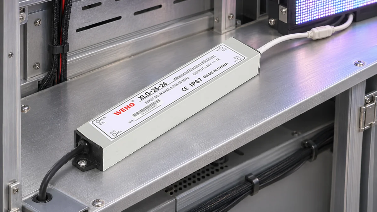
A Connector Can Mate Correctly While Its Polarity Is Wrong
A service connector can simplify replacement of a small lighting assembly, yet introduce a wiring error when its cavity locations are copied from the wrong viewing direction. The housings may latch normally even though the conductors occupy the wrong cavities.
For the WEHO XLG-25-24 lighting driver, this article considers a hypothetical OEM harness added outside the driver. It does not claim that the driver includes the illustrated connector, that its original leads should be modified, or that a connector's appearance establishes its electrical or environmental rating.
Keep the Driver Identity Separate From the Harness Design
The manufacturer's XLG-25 specification lists 24 V and 1 A for the XLG-25-24. At those nominal values, 24 × 1 = 24 W. The 25 W family name should not be used to turn this exact variant into a 25 W output rating.
Those source values identify one part of the circuit. They do not establish the pin assignment, contact rating, cable specification, sealing or mating suitability of an externally selected connector. These items belong to the equipment design and require their own supplier documentation.
Before drawing a pin map, record the connector housing and contact part numbers for both halves. Include any keying or coding option that changes which parts can mate. A catalog family name can cover several cavity arrangements, contact sizes or polarizing features.
A manufacturer drawing can explicitly identify front views and contact positions. For example, Molex's connector drawing separates male and female front views and their contact positions. This illustrates the need to read the specified view; it is not a recommendation to use that connector with the XLG-25-24.
Name the View Before Naming the Pin
“Mating face” means looking toward the contact interface of the component being documented. “Wire side” means looking from the cable-entry side. Looking through the same two-position component from the opposite end reverses the left-to-right appearance when the key is held at the same apparent top position.
Male and female are also incomplete orientation descriptions. A connector supplier may present each mating half from its own front view, so the drawing positions that connect together need not sit on the same side of two page illustrations. Follow the actual supplier's circuit numbering and mating information.
| Drawing field | Record explicitly | Why it changes the result |
|---|---|---|
| Component identity | Exact housing, contact and keying option | Similar shells can contain different arrangements |
| Viewing direction | Mating face or wire-entry side | The apparent left and right positions can reverse |
| Orientation feature | Key, latch or other defined reference | Rotating the drawing changes apparent location |
| Circuit assignment | Supplier cavity number and project function | A number alone does not identify positive or return |
| Mating relationship | Which actual contacts connect through both halves | Two front-view sketches are not a continuity result |
Use a single view convention on the production instruction where practical. If the instruction needs both faces, label each separately and show the same reference feature. Do not expect an assembler to infer the intended side from a perspective photograph.
Work Through a Mirrored-View Example
The following is a hypothetical harness example, not the pinout of any supplied WEHO connector. Assume a project selects a two-position connector and assigns cavity 1 to DC positive and cavity 2 to DC return. The supplier's mating-face drawing shows cavity 1 on the left with its key uppermost.
Viewed from the wire side of that same component, with the corresponding key orientation understood, the apparent left position is cavity 2. If an assembler copies “positive on the left” into a wire-side instruction without changing the view, the circuit assignment is reversed. The mistake comes from the view transfer, not from a change in the driver's output.
The project record should preserve “cavity 1 = DC positive,” not merely a left/right phrase. The latter has no meaning without the viewing direction and orientation feature. A photograph of the completed harness is useful only when it has those same references and enough detail to identify the actual cavities.
| Hypothetical check | Expected relationship | Evidence to record | Disposition |
|---|---|---|---|
| Plug cavity 1 | Project DC-positive conductor | View, cavity marking and continuity result | Hold if function cannot be traced |
| Plug cavity 2 | Project DC-return conductor | View, cavity marking and continuity result | Hold if the map was copied by color alone |
| Complete mating pair | Positive reaches receiver positive | End-to-end released-circuit check | Correct any reversed mapping before energizing |
| Replacement harness | Same released interface and revision | Part numbers and configuration record | Review changes before interchange |
This example does not assign a universal meaning to cavity 1 or any wire color. Actual polarity must come from the exact driver identification and the equipment circuit documents. Do not reuse the hypothetical numbering on a different supplier's connector.

Swipe horizontally on a small screen, or open the full-size diagram.
Verify the Assembled Circuit Before the First Powered Trial
- Freeze the component references. Attach the relevant connector drawings to the harness work instruction, including revision and part-number options. Verify that the assembly stock matches the released parts.
- Mark the viewing direction. Identify the key or latch and name the face on every pin-map image. Remove any instruction that gives only left/right locations without a defined view.
- Check the driver-side functions. Confirm the actual DC-output identification from the applicable unit documents. Keep AC-input conductors and protective-earth requirements outside the hypothetical two-position DC map.
- Trace the complete harness. With all relevant sources isolated under the equipment procedure, use an appropriate continuity check against the released circuit map. Prevent connected electronics or parallel paths from creating a misleading reading.
- Review the mating pair. Confirm that each intended function reaches the corresponding receiving terminal through the actual assembled pair. Do not stop after checking only one loose half.
- Release the recorded configuration. Retain the component references, view convention, check method and observed result before the authorized functional trial. A changed connector or harness revision needs the relevant checks repeated.
The connector-view worksheet provides fields for both the supplier cavity reference and the project function. It deliberately avoids preassigning actual product lead colors or a real connector pinout.
Continuity establishes the connection covered by that check. It does not establish current capacity, insulation coordination, contact retention or environmental sealing. A connector can have correct polarity and still be unsuitable for its installed duty.
Specify Service Conditions Along With the Pin Map
Record whether the connector is intended for assembly, de-energized replacement or a separately qualified load-switching task. Physical separability is not evidence that a contact may interrupt an energized DC load. The connector supplier's applicable ratings and the equipment design must establish that duty.
Also check strain relief, lead support and cable movement in the actual enclosure. Do not apply a guessed bend radius to the driver's leads or assume that an IP marking on one component transfers to an externally assembled joint. The finished joint needs evidence appropriate to its environment.
For a broader explanation of traceable circuit identification, use the separate power-supply polarity verification article. The additional decision here is the connector's viewing direction and mating relationship, which must survive transfer from drawing to assembly instruction.
Request the Correct XLG-25-24 Output Identification
For an XLG-25-24 harness application review, provide the full model, proposed external connector parts, circuit map and service conditions. Ask for the applicable lead-identification documentation and any relevant restrictions before changing the original lead arrangement. Keep the external connector's qualification with its own supplier record.
Engineering FAQ
Does cavity 1 normally mean positive?
No universal assignment can be assumed. Use the selected connector's numbering together with the equipment's released circuit map. This article's cavity assignment is a hypothetical example and must not be copied as a product pinout.
Why can two mating-face drawings appear reversed?
Each half may be shown looking toward its own contact face. Read the supplier's view and mating information, then verify the actual end-to-end connection rather than aligning left and right positions on the page.
Does a correct wire color prove the harness polarity?
No. A color is useful identification only when its function has been established for the applicable assembly. Verify the conductor's actual destination against the released map and preserve that result through assembly revisions.
Does correct continuity mean the connector can be unplugged under load?
No. Continuity verifies a connection, not a load-breaking rating. De-energized service and energized switching are different duties, and the selected connector and complete equipment need applicable evidence for the intended operation.



