Last Updated: October 3, 2026
Quick Answer: To install a DIN rail power supply, first confirm the exact model, ordered revision, supply and control-load requirements; then have a qualified installer follow the applicable isolation procedure and manufacturer mounting, protection and wiring instructions. The label and terminals face outward while the rear rail support engages the specified rail. Internal supply protection does not replace input-circuit or wiring protection. Finish with documented mechanical and electrical acceptance checks, not a visual assumption that the cabinet is ready to energise.
Knowing how to install a DIN rail power supply means more than snapping a component into a cabinet. An OEM panel builder needs a traceable connection between the ordered supply, its rail orientation, the protected input circuit, the actual DC loads and the commissioning record. A generic photograph or familiar housing is not an installation instruction.
This guide uses WEHO DR-120-24 as a documented mechanical example for 24 V auxiliary electronics. It does not claim that the supply powers a pump motor, a commercial-kitchen heater or an entire machine. The application illustrations are isolated preparation scenes, with disconnected terminals and dark equipment, not completed installations.
Establish the model and installation documents
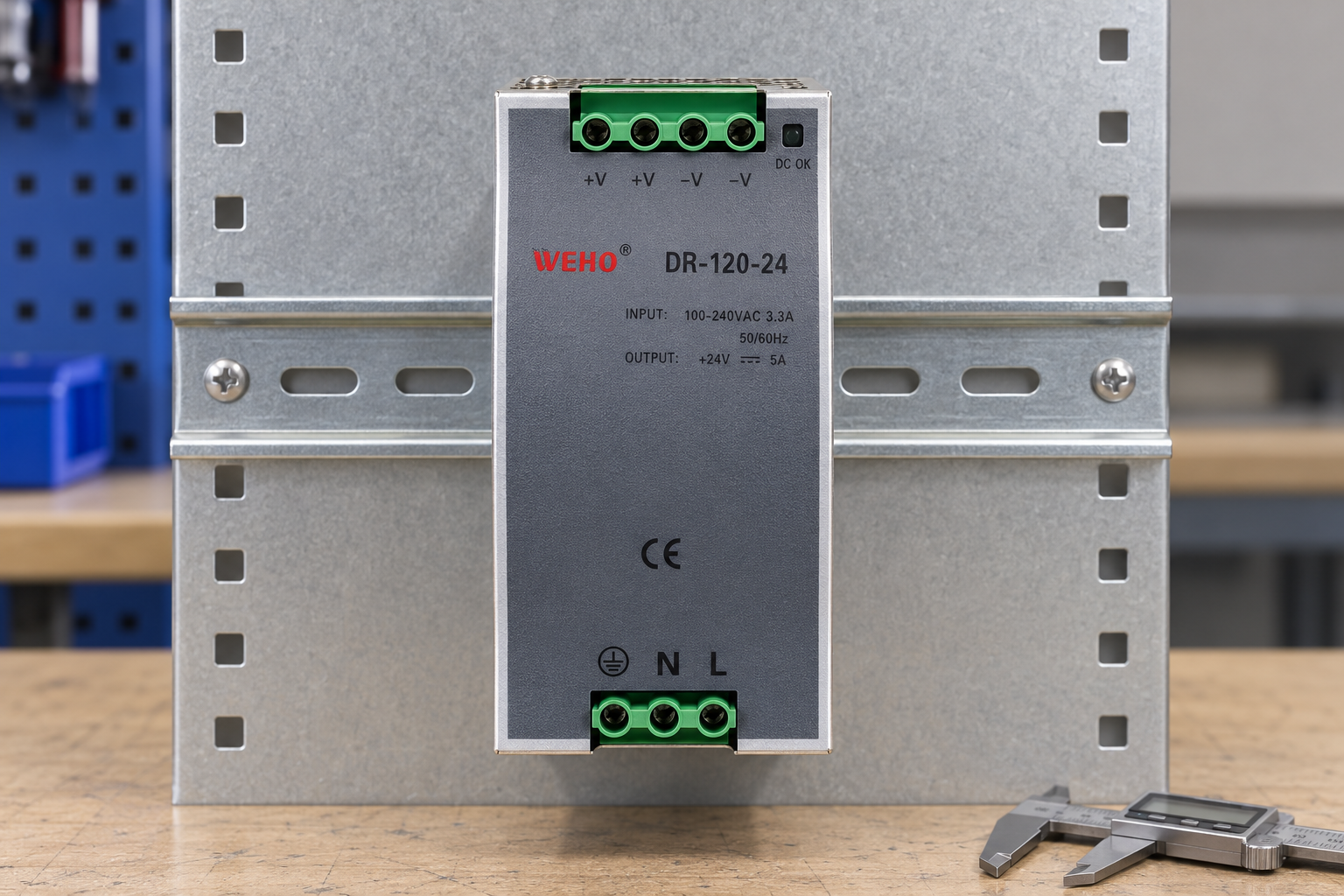
Match the received full model and revision to the purchase order, current specification, terminal drawing and any applicable mounting instructions. The WEHO DR-series category provides the family context; the exact source photo and current DR-120 specification identify the example as DR-120-24, rated 24 V and 5 A.
The documented envelope is 65.5 mm width × 125.2 mm height × 100 mm depth. Width is along the rail, height is upright and depth extends from the front toward the rear mounting plane. Add the installation’s required ventilation, wiring-bend and maintenance access outside this envelope. Do not confuse a product dimension with a guaranteed cabinet clearance.
The source label prints nominal input “100-240VAC 3.3A” and “50/60Hz”; the current specification separately lists an operating range of 85–264 VAC and 47–63 Hz. These are different document roles. Obtain confirmation for the ordered revision before accepting the site supply, rather than rewriting the physical label or automatically widening input acceptance.
Plan isolation, input protection and subsystem boundaries
Only a qualified person should perform installation and commissioning under the applicable site procedures and controlled manufacturer instructions. Identify every relevant energy source and possible backfeed, apply the required isolation controls and verification procedure, and manage any stored energy before mechanical or wiring work. This article is not a substitute for that procedure or a safe-to-touch determination.
Plan protection for the input circuit and conductors even when the supply contains internal overload or short-circuit protection. Internal protection describes a component function; it does not by itself establish suitable upstream circuit protection, conductor protection or selective fault isolation. The responsible electrical designer must specify protective devices, ratings and coordination using the actual supply, circuit conditions and applicable requirements. This guide does not prescribe a universal fuse or breaker size.
Define the DC subsystem separately from the machine’s main power. List controller, interface, sensor and other compatible 24 V demands, including simultaneous and startup states. Compare verified current and thermal conditions with the ordered model’s allowed operating limits. A 5 A nameplate does not establish available power for an unrelated motor or heating circuit.
Confirm the mounting face and rail engagement
On this source DR-120-24, the grey identity face, red WEHO mark and accessible terminals face the installer. The rear support is the mounting side. Reversing these faces can hide the identity, obstruct access and produce an unsupported arrangement. Do not attach the front face to the cabinet backplate simply because the metal case looks flat.
Confirm the specified 35 mm rail, its profile and fixation against the ordered unit’s drawing and installation instructions. Inspect the rail and support before fitting the unit. The exact clip operation and any release tool depend on the construction: a generic “hook the top and snap the bottom” description is not reliable evidence for every revision. Do not pry an unidentified latch or add an improvised front bracket.
After fitting, verify positive rear engagement and stability using the prescribed inspection method, without assuming that a unit resting against a rail is securely mounted. Confirm orientation, access and any specified spacing with neighbouring components. The fanless metal enclosure still needs its documented thermal conditions; ventilation openings are not cable-entry points.

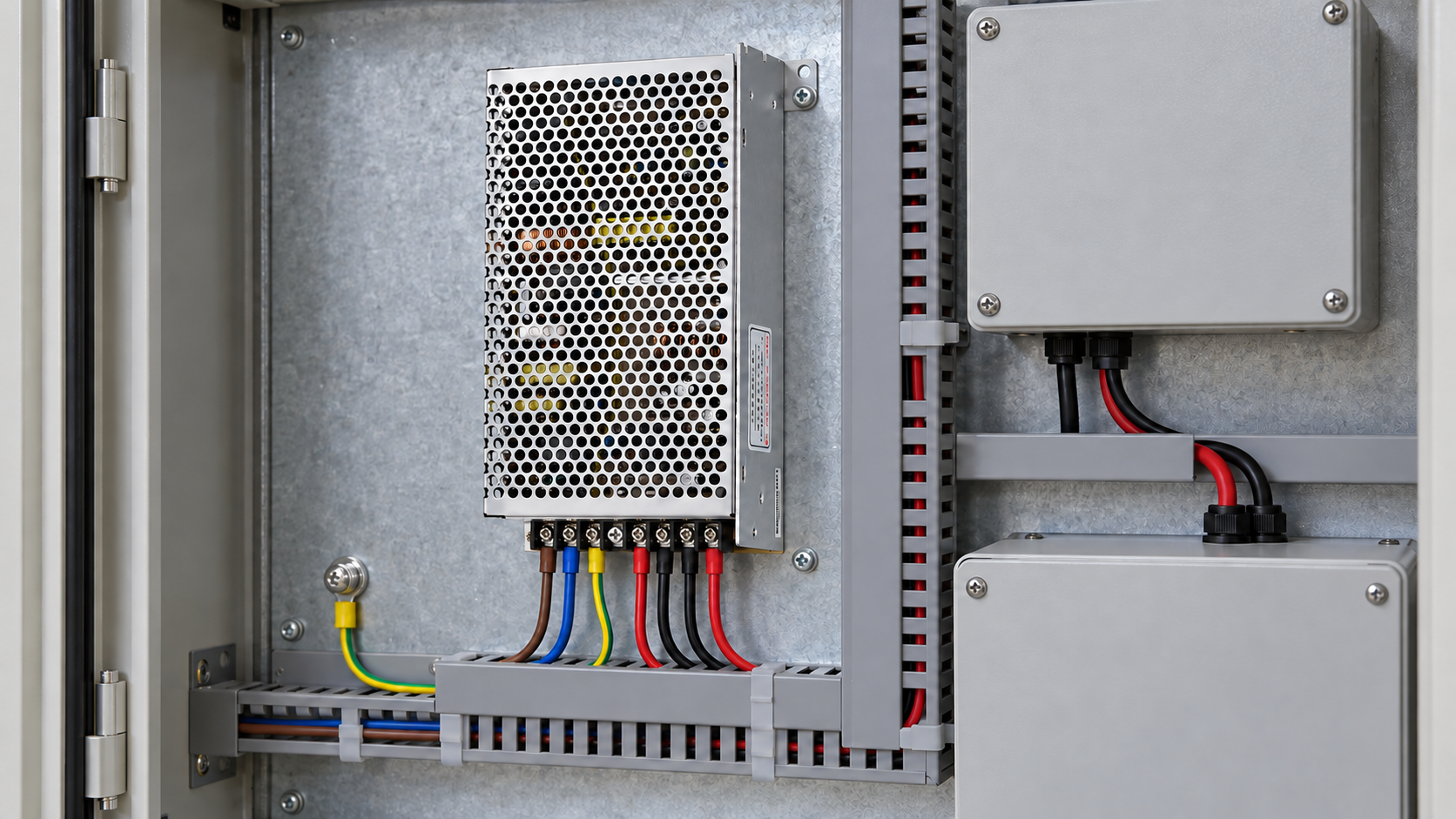
The first application illustration places the component in a protected dry workroom for water-treatment auxiliary controls. Tanks and piping establish the industrial context, but they do not prove environmental protection or pump compatibility. Verify the actual cabinet’s moisture, contamination and temperature conditions before selection. The pictured supply remains unwired and is not shown powering the pumps.
Use the exact terminal drawing for connection planning
The photographed DR-120-24 has four upper DC terminals, physically left to right +V, +V, −V, −V. Its three lower input terminals are protective earth, N and L. This is not the blue-front NDR model’s output order; similar names do not make the terminal layouts interchangeable.
Plan conductors, protective-earth connections, termination preparation, routing and tightening from the controlled instructions for the ordered revision. Keep input and output identification unambiguous. Do not invent conductor size or torque from the appearance of a terminal, and do not use a generated image as a wiring diagram. Repeated output terminals do not establish separate 5 A outputs; assess the connected total and permitted terminal use.
The source front has a small DC OK window at the upper right, but no front +V ADJ opening or legend. Do not transfer an adjustment procedure from another supply onto this one. If adjustment is required, obtain the correct ordered-unit documentation and access instructions rather than searching for or creating an imagined front control.

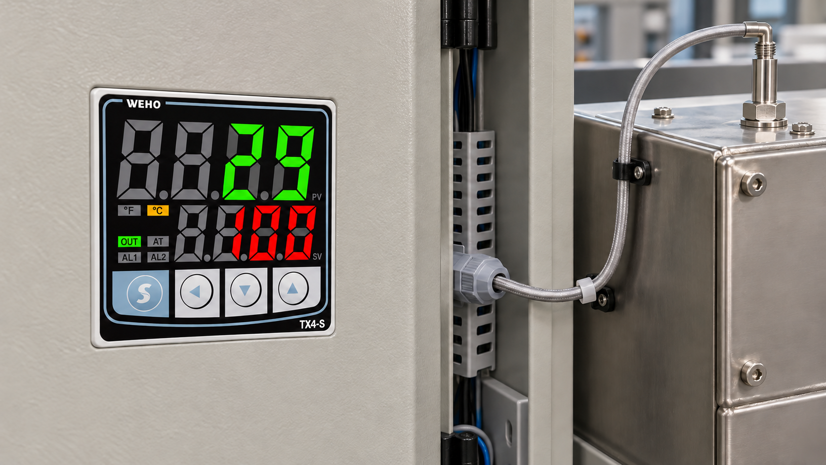
The second scene shows a modular commercial-kitchen equipment assembly bay, with an isolated control-panel fitting fixture beside stainless equipment casings. It concerns auxiliary electronics and access planning, not a claim that the supply operates heaters, fans or an appliance. This setting requires its own subsystem and environment review; it does not inherit approval from the water-treatment illustration.
Record acceptance before release
Before commissioning, complete the installation’s prescribed mechanical and electrical checks. The record should identify the exact unit and revision, rear rail engagement, orientation, terminal mapping, protective-earth arrangement, input protection, conductor terminations and unresolved questions. Use authorised procedures and suitable instruments; the installer determines what checks are safe and applicable at each stage.
Evaluate output at the actual connected control loads, including the demanding simultaneous state and any startup behaviour that matters to those devices. Confirm the required temperature and fault-recovery behaviour in the intended cabinet. Do not interpret a status indicator or an unloaded nominal-voltage reading as proof that every branch is acceptable.

Keep photographs, controlled drawings, applicable test records and deviations linked to the build. An illustration can help explain orientation, but cannot establish electrical safety, certification or completed commissioning. Hold release where the model revision, installation instruction or protection design remains unresolved, and ask WEHO for the missing controlled information.
Key Takeaways
- Keep the grey label face and terminals outward; the rear is the mounting side.
- Follow the ordered revision’s rail and clip instructions, not a generic snap method.
- Internal supply protection does not replace input-circuit and conductor protection.
- Verify DR-120-24 terminal order; do not borrow another model’s layout or controls.
- Document mechanical, electrical and thermal acceptance before release.
Conclusion
Knowing how to install a DIN rail power supply combines correct component identity with a verified mounting and protection design. DR-120-24 is a documented 24 V, 5 A auxiliary-control example, not a universal machine-power choice. Use the current documents for the ordered revision, retain installation and commissioning evidence, and resolve open questions with WEHO and the responsible project installer before releasing the panel.
Frequently Asked Questions
Which side of DR-120-24 faces outward when mounted?
The grey source identity face, red WEHO mark and terminals face outward. The rear support is the rail-mounting side. Confirm the ordered revision’s drawing and mounting instructions before fitting.
Can internal overload protection replace upstream input protection?
No such substitution is established. The responsible designer must provide the appropriate input-circuit and conductor protection and review coordination for the actual installation.
Is one generic hook-and-snap method correct for every DIN supply?
No. Rail profile, latch construction and release procedure depend on the ordered unit. Follow its controlled mounting instructions instead of improvising a clip operation.
What terminal order is visible on the source DR-120-24?
The four upper DC terminals run +V, +V, −V, −V from left to right; the three lower input terminals are protective earth, N and L. Use the controlled terminal drawing for actual connection planning.
Does this DR source have the NDR model’s front adjustment control?
No front +V ADJ opening or legend appears on the DR-120-24 source. Do not transfer controls or an adjustment procedure from another model; obtain the ordered-unit instructions if adjustment is required.
Do the images prove pump or commercial-kitchen compatibility?
No. They show isolated auxiliary-control mechanical preparation with empty terminals and dark equipment. They do not establish pump-motor, heater, appliance or environmental compatibility.
Does the product envelope include installation clearance?
No. The documented envelope is 65.5 mm width by 125.2 mm height by 100 mm depth. Ventilation, conductor bends and service access must be added according to the controlled installation requirements.