Direct answer: Adjacent inductive proximity sensors can influence each other and cause an unstable output even when each works alone. First compare their actual orientation and separation with the exact sensor manufacturer’s mutual-interference data. Then test the intended arrangement, with representative targets and all nearby sensors operating. Shielded construction and a single successful test do not prove that every spacing or production combination is acceptable.
Separate surrounding metal from another active sensor
Metal brackets and nearby moving parts may change an inductive sensor’s response. Mutual interference is a different question: one active sensor affects another. The Omron explanation discusses interaction between nearby oscillators. Its description is not a claim about a particular WEHO model. Record the mounting metal and target as well as which neighboring sensors are powered so the two causes are not confused.
Why does orientation matter?
Manufacturer clearance tables may distinguish sensors mounted side by side from sensors aimed face to face. Omron’s spacing FAQ illustrates this distinction for its listed products and optional frequency variants. Do not use its distances as universal clearances for LJA18, and do not assume a WEHO frequency variant exists. Obtain the requested model’s own instructions, including the measurement reference points.
Use a repeatable comparison, not a guess
| Condition | Keep constant | Observe |
|---|---|---|
| A only energized | Sensor A, target, bracket and supply | Output and operating/reset positions |
| A and B energized | Same target travel and speed | Any new false switch, chatter or shifted threshold |
| Changed separation or orientation | Same sensors, metal and target | Whether the documented design margin is met |
| All intended sensors active | Normal production arrangement | Interactions across the whole group and representative parts |
Authorized personnel should perform any moving-target or machine-motion checks under the equipment’s approved controlled test procedure, using suitable instruments and protective arrangements. A difference when B is enabled suggests an interaction, but is not by itself a complete root-cause diagnosis: also check supply, load, wiring, cable routing and surrounding metal. A neighboring sensor may affect measurements in either direction, so record actual outputs rather than assume a particular symptom.
How to qualify a closely spaced design
- Identify the complete order codes and any documented frequency variants of each sensor; record the installed distances, reference faces and orientations.
- Request model-specific separation and mounting data, including limits for the bracket material and target arrangement.
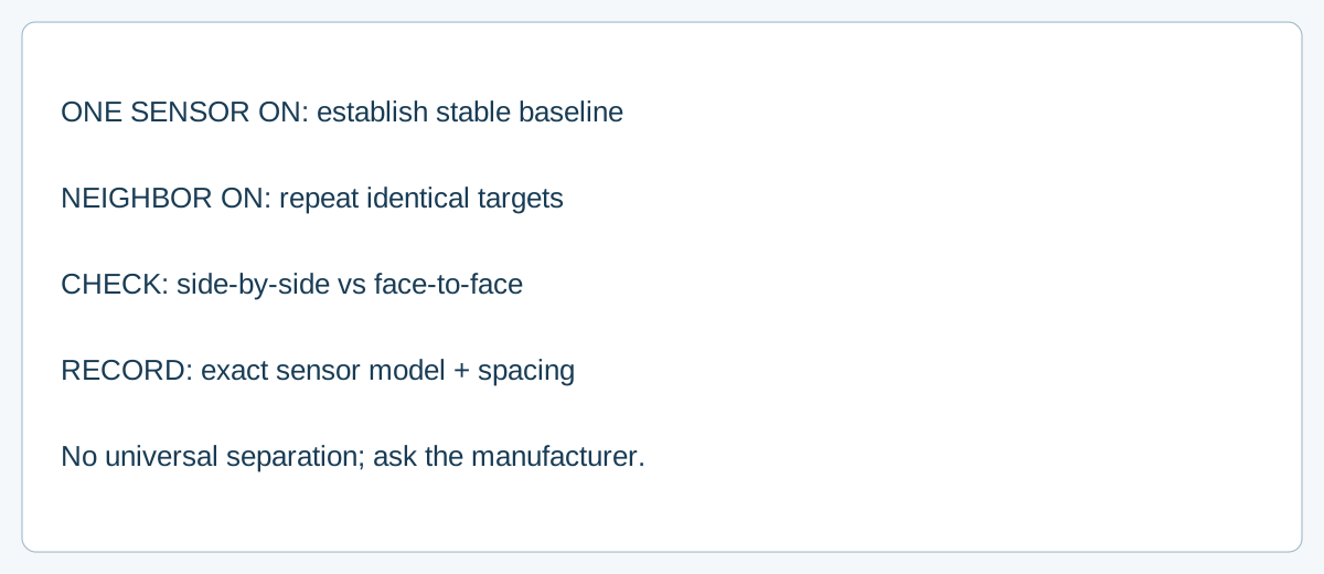
- Establish a baseline with one sensor energized. Repeat with neighbors on individually and in the final combination; test representative targets and travel throughout the operating envelope.
- Review supply voltage and temperature conditions and record the actual sensors tested. Omron notes unit-to-unit oscillator variation in its close-spacing FAQ; an isolated passing sample is not proof that every future combination passes.
- If clearance is unavailable, ask the manufacturer whether alternative models, spacing, shielding arrangements or verified frequency options are appropriate. Requalify any change to position, sensors or nearby metal.
Do not alter an installation solely on an unrelated manufacturer’s frequency-pairing rule. A specific clearance or approved combination must come from documentation for the actual units and their operating conditions.
Where the WEHO product fits
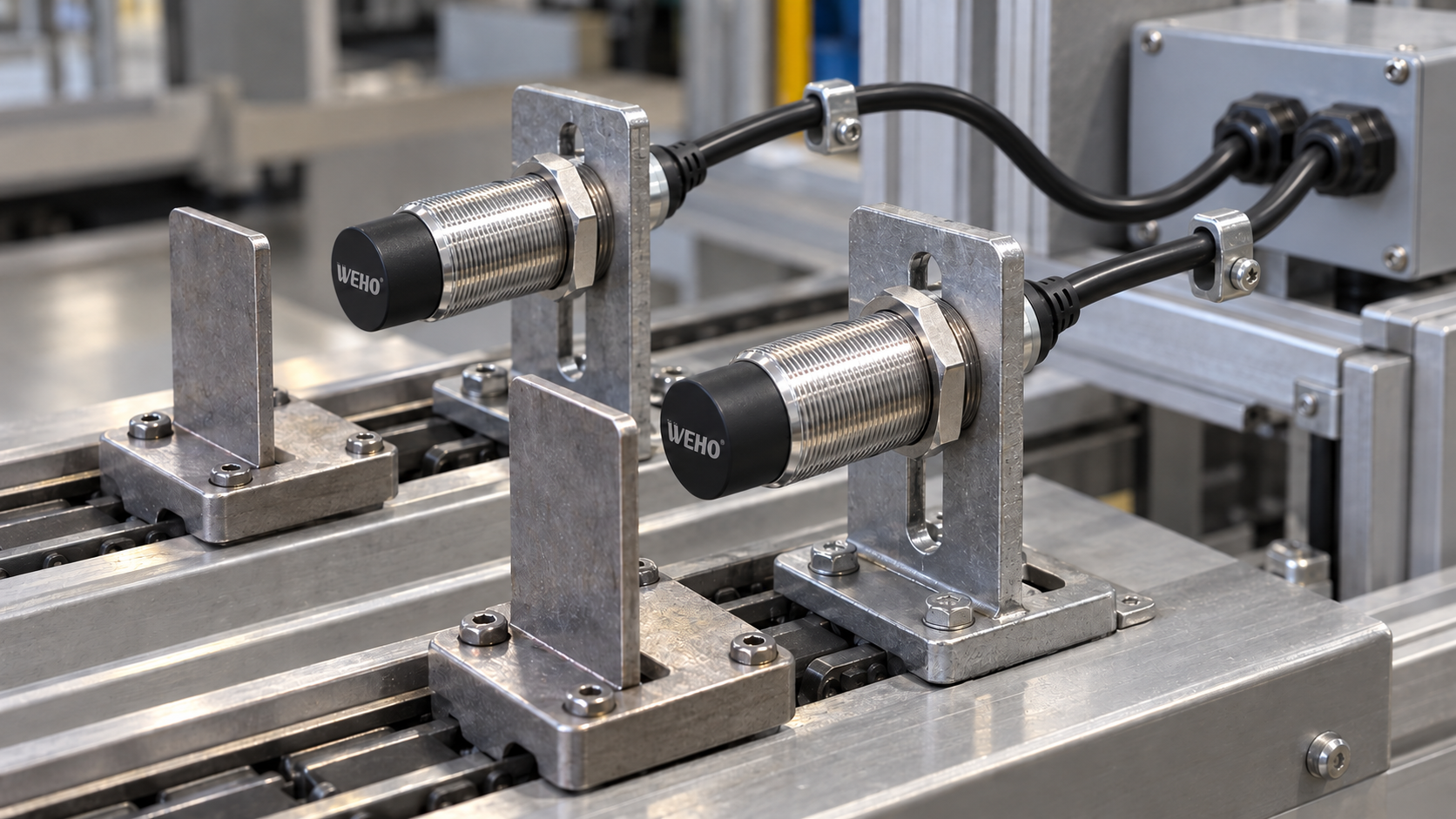
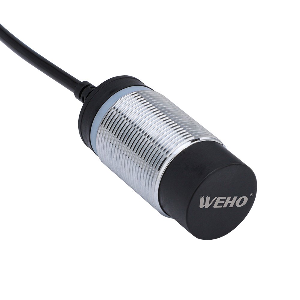
The WEHO LJA18 product page presents an inductive proximity sensor family. The shown official product image identifies the family appearance, not an exact electrical suffix, approved adjacent-sensor spacing or a verified production setup. Supply the full intended order codes and mechanical drawing when requesting a clearance review.
Frequently asked questions
Does an indicator that works alone rule out interference?
No. Compare the output with neighbors energized, the actual targets moving and the final mounting arrangement in place.
Can I use another brand’s distance table?
No. Its model, orientation, frequency options and reference dimensions may differ. Request applicable evidence for each installed sensor.
Send WEHO the full LJA sensor variants, intended side-by-side or face-to-face arrangement, measured mounting dimensions, surrounding metal and target material. Request the model-specific interference and mounting guidance before releasing the layout. Contact WEHO.