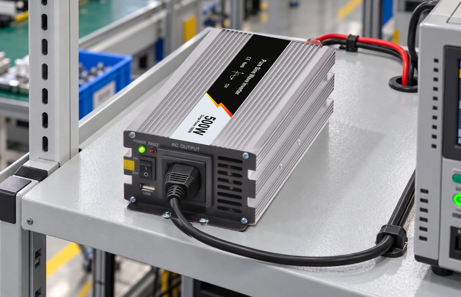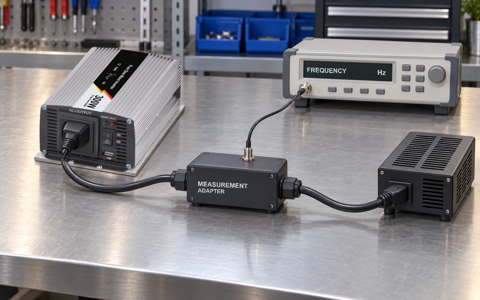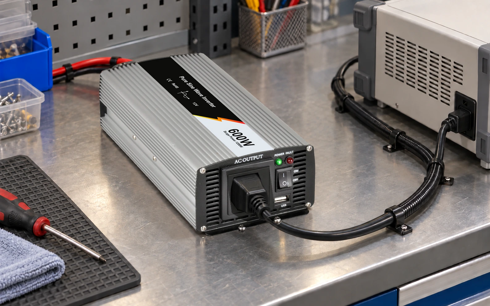
Check the voltage where the AC load receives power, as well as at the inverter outlet, under the same operating condition. An extension lead adds conductor and connection impedance. A correct outlet voltage can coexist with an unacceptable voltage at the remote appliance.
This guide gives an integrator an AC-side route calculation and observation record using the WEHO WHP600W family as a product reference. It does not replace battery-cable design or establish that an arbitrary reel, adapter or appliance is suitable.
Define the complete AC extension route
Record the one-way cable length, conductor material and cross-section, permitted current, insulation/environment conditions and every plug, coupler or distribution accessory. Include the return conductor in resistance calculations. A20m lead usually creates about 40m of outgoing-and-return conductor path for this simple single-phase calculation.
Use the receiver’s documented or measured RMS current. Real watts divided by nominal voltage can understate current when power factor is below unity. Capture changing demand as well as a light-load reading if the equipment cycles.
Inspect and use the lead according to its instructions. The current permitted on a reel may depend on its deployed condition; do not assume a wound reel has the same thermal rating as a fully deployed one.
Calculate a resistance screen with clear assumptions
For a short, predominantly resistive single-phase route, an initial screen isRloop=ρ×2L/A, followed byΔV≈I×Rloop. Use an appropriate conductor-temperature resistance value, and treat connector resistance separately. Longer or more reactive routes need a more complete AC calculation.
Hypothetical example: assume copper resistivity 0.0175 Ω·mm²/m at 20°C,20m one-way length,1.5 mm² conductors and 2.5 A RMS current. Cable loop resistance is 0.467 Ω and the estimated resistive drop is 1.17 V, about 0.51% of 230 V. Cable I²R loss is approximately 2.92 W. These numbers exclude hot-conductor increase and contact losses; they are not a cable-size recommendation.
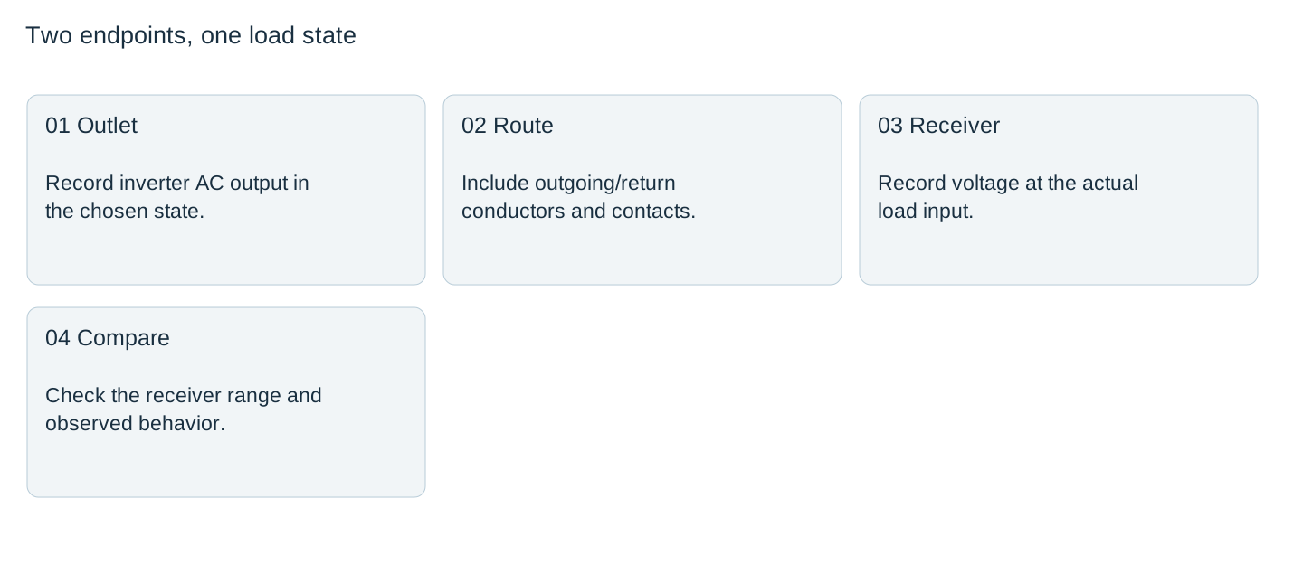

Compare the result with the receiver’s actual input range and the applicable installation requirements. A convenient percentage target is not a substitute for those limits.
Keep the inverter and lead limits separate
The WHP600W page lists 600 W rated power and 1200 W peak power, with AC output options presented separately. Confirm the actual supplied AC voltage and frequency before using them in a route assessment. The official image shows a 600 W/12 V example; it does not establish a different input option or the capability of a connected extension lead.
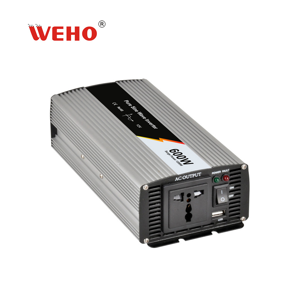
Victron’s AC cabling discussion explains that voltage drop and connection heating also occur on AC circuits. Its installation examples and component instructions apply to the products described there; they are not WHP terminal instructions or a universal cable-sizing rule.
Compare both endpoints during a controlled load state
Have qualified personnel establish a suitable measurement arrangement without exposing live contacts. Record inverter-outlet voltage and receiver-input voltage for the same load state. If the load changes rapidly, unrelated readings taken at different times cannot establish the route’s drop.
Retain the AC current, output frequency, instrument method, lead configuration and temperature conditions. A distorted waveform or a short interruption may require more information than a slowly updating voltage display. Specify receiver behavior as well: did the device remain within its input limits and complete its intended cycle?
If outlet voltage is satisfactory but the receiver voltage falls, investigate the downstream route and contacts. If both fall together, the lead alone cannot explain the observation. Preserve the evidence rather than replacing parts from a single reading.
Release the exact extension configuration
Use the worksheet to connect the resistance estimate to actual endpoint measurements. Identify the permitted lead, maximum route length, load list and required deployed condition. Include the relevant cordset and accessory identities so a service replacement remains within the reviewed configuration.
A warm or damaged connector needs investigation even if the total voltage drop appears small. Do not raise protective-device ratings to accommodate an unsuitable cable or connection. The required protection and installation remain the responsibility of the complete system design.
Repeat the affected checks when the route length, conductor size, accessory, current demand or operating environment changes. This keeps an AC distribution issue from being misreported as an inverter power defect.
Send the AC route and receiver conditions
When discussing WHP600W integration with WEHO, include the ordered output option, remote receiver requirements, AC current evidence and extension-route details. Keep the battery-side cable review as a separate part of the project.
AC extension endpoint-voltage record
| State | RMS current | Outlet voltage | Receiver voltage | Drop / receiver result |
|---|---|---|---|---|
Blank project worksheet. Enter verified project data; example calculations above are not measurements.