Parallel power supplies increase available output capacity only when their documented operating method supports the arrangement. Redundant power supplies must also keep the required load powered after a defined source failure. Current sharing controls how healthy supplies divide demand; reverse-current decoupling helps stop a failed branch from loading the healthy branch. For an OEM cabinet, choose the architecture by calculating remaining usable capacity, checking the complete failure path, and testing bus voltage and alarms with each source unavailable.

Table of Contents
Distinguish parallel capacity, current sharing, decoupling, and redundancy
Two 24 V units beside one another do not establish what happens when an output cable opens, an input disappears, or a supply develops an output fault. Start by writing the requirement: more current during normal operation, continued operation after one source is lost, or both.
| Function | Question it answers | Evidence to request |
|---|---|---|
| Parallel capacity | Can the connected supplies serve the total normal demand? | Permitted models, connection method, maximum unit count, output settings, and operating limits |
| Current sharing | How does each healthy source carry its share? | Sharing method, tolerances, load dependence, cable requirements, and behavior when a unit reaches its limit |
| Reverse-current decoupling | Can one failed or unpowered path drag down another? | Isolation method, reverse-current limits, fault coverage, current rating, voltage drop, and thermal limits |
| System redundancy | Does the specified load remain valid after the named failure? | Remaining capacity, voltage at the load, independent paths, alarm coverage, and system test results |
Two voltage-regulated outputs with slightly different setpoints may carry unequal currents. Permission to connect outputs in parallel and controlled current sharing are separate specifications, as explained in this external technical note on paralleling and redundancy. Equal nameplates alone do not ensure equal currents.
Use only a connection arrangement supported by the exact supply and decoupling-device documentation. Adding an external ORing stage does not automatically make an otherwise unsuitable supply arrangement compatible.
Calculate N+1 redundant power supply capacity after one failure
For identical modules, a first continuous-capacity check is:
- Remaining current = (installed module count − 1) × permitted continuous current per module
“Permitted” means the current available at the chosen voltage and actual input, temperature, mounting, and cooling conditions. It also assumes the manufacturer permits that many units and that the distribution stage can carry the result. Use the derating conditions before doing redundancy arithmetic.
Consider a hypothetical 24 V cabinet requiring 12 A continuously. Each candidate module has an assumed usable capacity of 8 A under the cabinet conditions, with compatible sharing and decoupling already established.

| Arrangement | Normal usable capacity | After one module is lost | Continuous-load conclusion |
|---|---|---|---|
| Two 8 A modules | 16 A | 8 A | Can cover 12 A normally; cannot maintain the full 12 A after one loss |
| Three 8 A modules | 24 A | 16 A | Clears the 12 A continuous-capacity check by 4 A |
| Two 8 A modules; 7 A critical bus | 16 A | 8 A | Clears the 7 A critical-load check if other loads are reliably removed |
In the three-module example, two modules are required to carry 12 A, so the capacity arrangement is N+1 with N = 2. Normal sharing would be 4 A per module if equal; after one loss it would be 6 A per survivor. Those are ideal averages, not guaranteed sharing measurements. Startup peaks and the transfer transient still need separate acceptance criteria.
Budget the decoupling path at the load
A redundancy module consumes voltage and produces heat. Its terminals and common output may carry the entire critical-load current even when each source normally carries only part. Compare the module’s continuous and transient limits with both operating states.
For a hypothetical voltage check, assume the minimum source-terminal voltage is 24.0 V, the maximum decoupling drop at the relevant current is 0.35 V, and the remaining cable and connection drop is 0.45 V. Then the load receives 24.0 − 0.35 − 0.45 = 23.20 V. If the load’s documented minimum is 21.6 V, the calculated steady-state margin is 1.60 V. Recalculate the drops at the higher surviving-path current; normal-state drop cannot stand in for the one-source-out case.
This is the same accounting used in a complete DC voltage budget, with the decoupling element added explicitly. The test must capture brief dips too: a satisfactory average bus reading can hide a controller reset during transfer.
Ask for separate instructions covering parallel capacity and redundancy, including the response to an output short. For a manufacturer example of that documentation, see the external power-supply datasheet, revision 1.4, sections 26.6–26.7. Apply each candidate’s own instructions when checking its permitted arrangement.
Define which failures the cabinet must tolerate
List failure cases before selecting hardware. “One module unavailable” is narrower than “one supply path unavailable.” Two supplies sharing the same upstream breaker remain exposed to that breaker opening. Separate upstream sources can reduce that particular exposure, but only if the installation actually provides the required independence.
Review common points such as a shared disconnect, terminal block, ORing output, cabinet fan, grounding connection, and load cable. Two sources in one overheated enclosure can suffer the same environmental event. Redundancy also does not isolate a short on the common load bus; branch protection and selectivity remain separate design tasks.
State the intended response for each case: continue all loads, keep only a defined critical group operating, initiate a controlled shutdown, or stop. If load shedding is required, include its detection time, switching behavior, and failure state in the design. Do not count an operator action that occurs later as immediate spare capacity.
Test each surviving path and expose hidden failures
Define accessible isolation points in the cabinet test plan, then use the manufacturer’s instructions and a qualified procedure to remove one source at a time. Check the intended source-loss response without creating an internal short.
- Record supply models and revisions, settings, load state, temperatures, and current in every source path.
- Remove Source A by the approved isolation method. Check the named load-terminal voltage and the surviving path’s continuous and transient current.
- Confirm that the expected source-failure alarm reaches the control system. A healthy common-bus indicator alone cannot establish that the spare path is available.
- Restore the source, check recovery and current distribution, then repeat for Source B and each additional source.
- Evaluate other required failure cases separately, including upstream loss and distribution faults, with methods appropriate to their energy and fault conditions.
Preserve the configuration and results so a later load increase does not silently remove redundancy. A system that passes at 7 A may no longer meet its one-failure requirement after additional equipment is fitted.
Turn the architecture into a useful WEHO inquiry
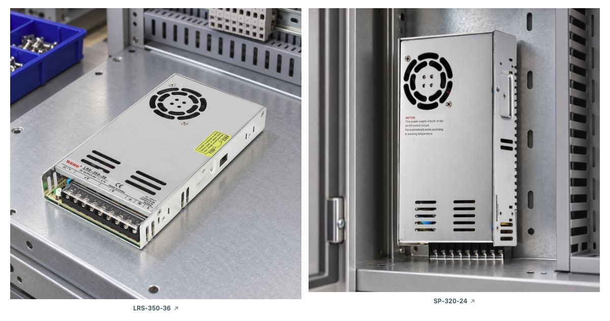
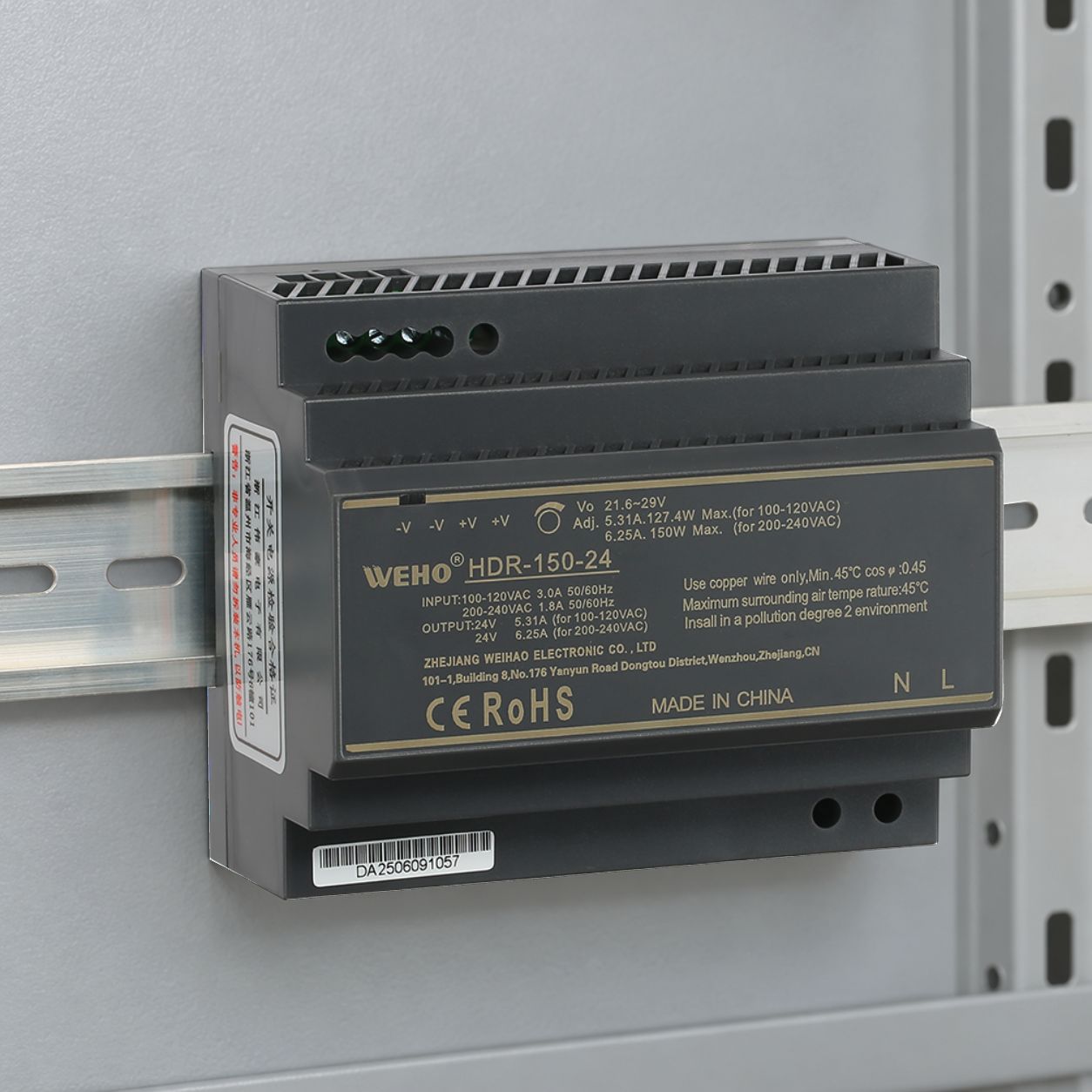
For the pictured NDR-240-24 appearance samples, the NDR-240 product details and public NDR-240 specification provide an identity reference only; they do not approve parallel operation, current sharing or redundancy. State whether the project needs added capacity, one-source redundancy, or both. In the inquiry, distinguish a proposed external diode/MOSFET ORing stage from a requirement for an exact model with documented parallel operation. Ask which candidate output characteristics and connection limits support the proposed topology.
An external ORing device and current sharing solve different problems. The design review needs the supply and decoupling-device documents together, including permitted unit count, output settings, voltage loss, reverse-current behavior, and installed temperature limits. This makes the architecture part of the initial model review.
Contact WEHO about the required source-failure response. Include the critical-load current, input-source arrangement and cabinet temperature, plus a sketch of the failure the equipment must tolerate. An early concept sketch is enough to frame the inquiry; complete the capacity and source-out test record when a documented hardware arrangement is identified.
Optional project record: Download the surviving-capacity worksheet (CSV). Use it to record your own inputs and evidence; example entries are illustrative.