



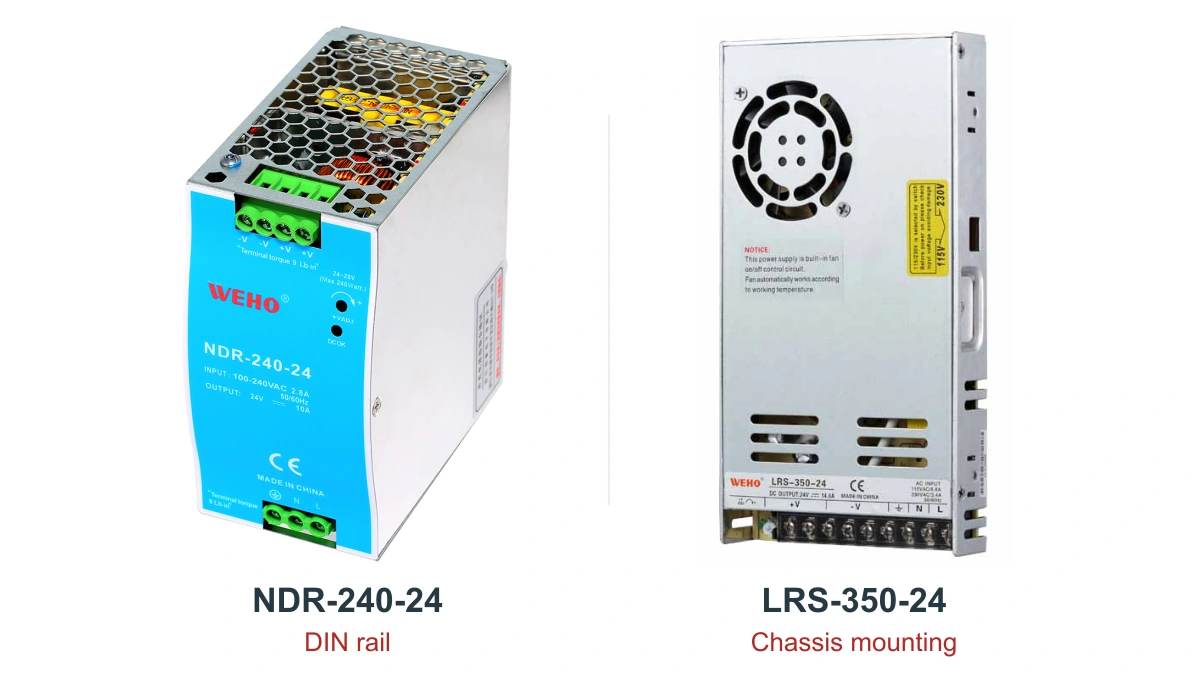
Choose a DIN rail or chassis-mounted enclosed power supply by comparing its complete installed space, cooling conditions, and replacement path. DIN rail mounting can suit modular control rows; a chassis format can suit a shallow equipment tray or mounting plate. Neither format is automatically smaller, cooler, or easier to service. First confirm that both candidates meet the electrical requirement, then compare the space and installation evidence for the exact models.

Table of Contents
DIN rail, enclosed, and chassis mounting describe different features
DIN rail describes a mounting interface. Enclosed describes a housing around the power conversion assembly. A DIN rail power supply can also have a metal or plastic enclosure. In an OEM comparison, the useful distinction is usually a purpose-built DIN rail unit versus an enclosed unit fastened to a chassis or mounting plate.
Keep that distinction on the drawing and purchase specification. A ventilated metal cover does not establish a sealed environmental barrier, and an accessory rail clip does not automatically make a chassis unit an interchangeable DIN rail product. Any adapter must have a documented support arrangement and preserve the supply’s permitted installation conditions.
Start the electrical shortlist separately with the required input, output, load profile, isolation requirements, and fault response. The 24V control-panel sizing example explains the load schedule. This comparison starts after that requirement is known; it asks which physical format fits a repeatable machine build.
Original photographs: two mounting formats


Compare the installed envelope, not the housing volume
A compact body can require a large working space. Draw the housing, support, conductors, adjacent duct, door equipment, and tool access in the same coordinate system. Identify the reference plane for depth: the mounting plate, the rail surface, or the back of the supply. This prevents counting the rail twice or leaving it out entirely.
| Check | DIN rail candidate | Chassis-mounted candidate |
|---|---|---|
| Support | Exact rail profile, latch engagement, rail support and permitted orientation | Specified base or side fixings, support plane, fastener size and penetration |
| Occupied space | Body width and height, installed rail projection, terminal access and duct separation | Body footprint and height, fixing access, bracket projection and terminal approach |
| Cooling space | Required top, bottom and side clearance around the actual neighbors | Documented vent or fan inlet/outlet clearance in the selected orientation |
| Removal | Latch-tool approach and the movement needed to disengage the rear mounting | Fastener-tool approach and withdrawal of the unit or service tray |
| Harness | Conductor entry, bend radius, terminal access and usable slack | The same checks, including any cover that must move during replacement |
Include dimensions, mounting alignment, and installation spacing in the shortlist. Keep each candidate’s required clearances with its own drawing, including space for terminals, conductors and removal; an allowance used for one model is not a cabinet-wide rule.
Check the cooling method and enclosure boundary
Convection cooling relies on moving air, even when no fan is fitted. A cable duct above the outlet, a hot drive below the supply, or an installation rotated to save width can change that airflow. This manufacturer’s convection-cooling guide explains why the inlet and outlet need attention.
For each candidate, obtain the allowed continuous output at the cabinet’s local air temperature, minimum input condition, and actual mounting direction. The referenced mounting guidance illustrates how orientation can affect loading. Use the candidate’s own instructions and the temperature, altitude, and mounting derating method to compare usable output on the same basis.
Also identify which enclosure protects the completed equipment from access, dust, liquid, and loose objects. The supply’s own cover and the machine cabinet perform different jobs. A mounting choice cannot establish the completed assembly’s environmental rating, protective-earth arrangement, or acceptance of exposed terminals.
Worked example: the narrower supply does not fit the depth
Hypothetical layout example: an OEM has two mounting zones: a DIN row with 90 mm width × 210 mm height × 145 mm depth from the mounting plate, and a horizontal tray with 200 mm width × 230 mm length × 90 mm vertical clearance. Both candidates are assumed to meet the electrical requirement. The following body dimensions and layout reserves are illustrative, not WEHO dimensions or manufacturer-required clearances.

Candidate A has a 60 × 125 mm front and a 115 mm body depth measured from the rail’s front mounting surface. The assumed rail projection is 7.5 mm. Its layout reserves 10 mm on each side, 40 mm above and below, and 25 mm in front for the selected harness.
Candidate B is mounted flat on the horizontal tray. Its body is 160 mm wide × 100 mm long × 35 mm high above the tray base. Reserve 10 mm at each lateral side. Along the 100 mm length axis, reserve 20 mm at the rear end and 30 mm at the opposite terminal end. The 25 mm allowance above the cover adds to the 35 mm vertical height. Thus, the DIN comparison uses width × height × depth; the flat-tray comparison uses width × length × height.
| Axis check | DIN candidate A | Flat-tray candidate B |
|---|---|---|
| Required width | 60 + 10 + 10 = 80 mm | 160 + 10 + 10 = 180 mm |
| DIN height / tray length | 125 + 40 + 40 = 205 mm | 100 + 20 + 30 = 150 mm |
| DIN depth / tray height | 115 + 7.5 + 25 = 147.5 mm | 35 + 25 = 60 mm |
| Available zone | 90 × 210 × 145 mm | 200 × 230 × 90 mm |
| Initial result | 2.5 mm too deep for the assumed row | Fits the assumed tray envelope |
The 60 mm-wide candidate loses its apparent advantage when installed depth is included. The next decision is to revise the DIN row arrangement, select a shallower candidate, or advance the chassis option to a physical fit trial. Do not recover the missing space by reducing a required cooling clearance or forcing a tighter conductor bend. The tray result still needs a separate removal-path and thermal check.
Include assembly and replacement in the format decision
For repeat builds, compare what the assembler actually does: fit and support the rail or tray, install the supply, terminate the harness, secure the conductors, and complete inspection. Record the hardware and tools each candidate requires. A low unit price can be offset by an additional fabricated bracket or an awkward assembly sequence; no standard labor saving applies to every DIN rail design.
Then walk through a de-energized replacement with a representative assembly. Can the latch or fasteners be reached without removing unrelated equipment? Can the terminal cover open? Does the harness have a controlled place to move? Can the replacement be identified and reconnected without relying on conductor color alone? These questions turn “easy maintenance” into an observable requirement.

If a candidate uses a fan, include its documented maintenance and replacement arrangement. If it does not, retain the cooling clearances in the service drawing. For a later substitute, repeat the mechanical and electrical compatibility review; sharing a mounting format does not make two supplies interchangeable.
Start a mounting-format shortlist with WEHO
Compare the DIN rail and chassis-mounted product references linked above using the complete installed arrangement. You can begin an inquiry with a space sketch rather than a completed cabinet drawing. For each candidate carried forward, check its drawing and installation instructions for orientation, cooling space, fixing arrangement, and terminal access.
Before freezing the layout, compare usable output and the full installed arrangement, including the service route. A marked cabinet section is useful when the drawing leaves a depth reference or adapter arrangement unclear.
Contact WEHO about mounting-format candidates. Start with four items: input voltage range; required output voltage and load; available mounting space; and a sketch of the orientation and cooling arrangement. Add a candidate model if you already have one.
Optional project record: Download the installed-space comparison sheet (CSV). Use it to record your own inputs and evidence; example entries are illustrative.




