An adjustable switching power supply needs a released voltage setpoint, an allowed adjustment window and a final check at the loads. Turning the trimmer until one device works is not a repeatable commissioning method. The same change can overvoltage a nearby branch, alter available current at a power limit, or hide a distribution problem.
On this page
This guide uses a 48 V calculation to help OEM engineers define a factory adjustment instruction. It separates a local output trimmer from remote sensing and programmable control, then turns the chosen setting into a record that production and service can reproduce.
Identify the adjustment on the exact model
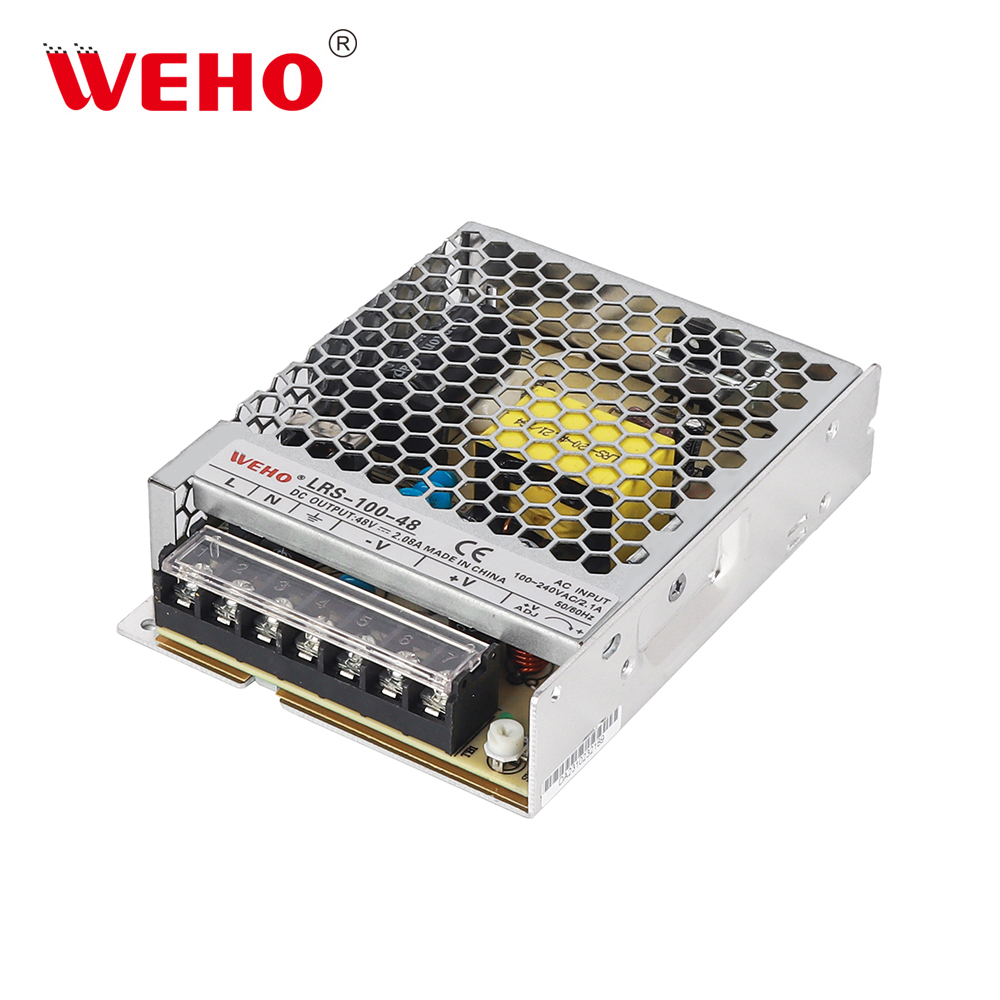
The WEHO LRS-100-48 switching power supply is a useful document-review candidate: published LRS-100 sheets include a DC-voltage adjustment field and an SVR1 location. The documents confirm adjustment exists; they do not make the supply a programmable laboratory instrument or establish a remote-sense interface.
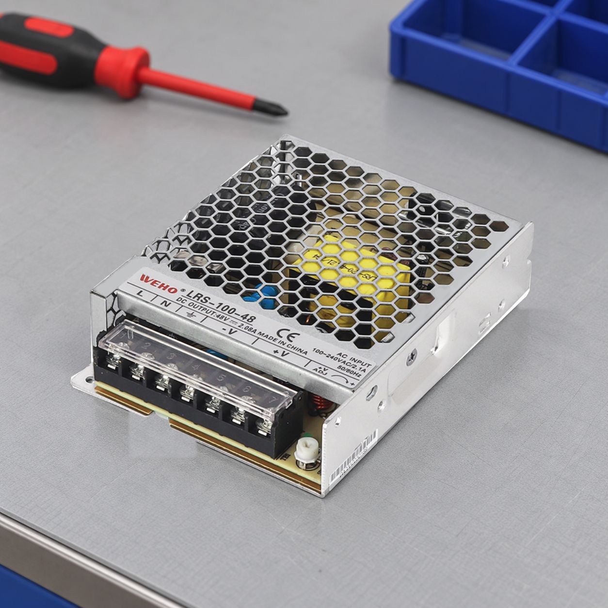
The LRS-100-1 sheet lists ±10% DC adjustment for its 48 V row; the separate LRS-100 sheet gives 43.2–52.8 V, the same interval. These archive documents corroborate adjustment capability. However, the photographed specimen is labeled 48 V, 2.08 A, while the older tables list 2.3 A for that suffix. Do not transfer the older current rating to this specimen. Obtain its applicable voltage–current–power envelope before releasing the setting.
Build the system’s allowed setting window
List each receiver’s permitted voltage at its own input terminals. Include source variation, outward-and-return distribution loss and measurement uncertainty. Separate steady-state limits from startup and load-change limits; a successful meter reading addresses only the condition actually measured.
For a simple calculation, assume the released source voltage can be held within ±0.20 V of a chosen setting S over the stated conditions. These are hypothetical bounds, not LRS-100 ratings. Load A requires at least 46.0 V and can lose 2.0 V in its distribution path. The low-side condition is S − 0.20 − 2.0 ≥ 46.0, so S must be at least 48.20 V.
Load B has a permitted maximum of 49.00 V and, for the limiting high-voltage case, negligible distribution loss. Its condition is S + 0.20 ≤ 49.00, so S must not exceed 48.80 V. The shared setting window is therefore 48.20–48.80 V. Choosing 48.50 V gives 46.30 V at A’s assumed low corner and 48.70 V at B’s assumed high corner. Those margins still need to meet the project’s required reserve.
| Boundary | Example condition | Result for S |
|---|---|---|
| A minimum voltage | S − 0.20 − 2.0 ≥ 46.0 V | At least 48.20 V |
| B maximum voltage | S + 0.20 ≤ 49.00 V | No more than 48.80 V |
| Shared solution | Intersection of both conditions | 48.20–48.80 V |
If B’s maximum were 48.20 V, its upper setting bound would become 48.00 V. The window would be empty. More trimmer adjustment would not solve that distribution design; the rail or harness arrangement would need review.
Check the power envelope after adjustment
Keep output current and output power as separate limits. In another calculation example, assume a source has a documented 100 W ceiling and a separate 2.5 A ceiling. At 52 V, the power limit alone gives 100 ÷ 52 = 1.92 A. It would be wrong to retain 2.5 A merely because the current rating was valid at a lower voltage. This example does not assign either ceiling to LRS-100-48.
Check the actual model’s stated adjustment conditions, thermal derating and load requirements. Revisit protection coordination and receiver limits where a higher setting changes the fault voltage or branch behavior. Adjustment capability does not imply constant-power regulation throughout the range.
Write an instruction production can repeat
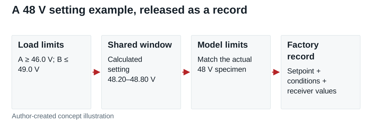
Specify the exact assembly and document revision, the measurement points, input condition, load state, stabilization condition, target and acceptance band. Define who may change the setting and when the complete acceptance check must be repeated. Use the manufacturer’s permitted adjustment method; do not turn this record into instructions for opening or modifying a supply.
Record the final value together with meter identity, relevant uncertainty and the receiver voltages. A tamper mark or label, where permitted, records configuration intent; it cannot prove that the voltage remained correct after a load, harness or supply change.
Release the setting with the equipment configuration
Include normal running, minimum demand, maximum demand, startup and the agreed input boundaries in validation. A technician should be able to tell whether a replacement needs the same setpoint or a new engineering review. Keep the accepted supply revision and harness definition attached to that decision.
Send WEHO your required voltage-setting window with load limits, distribution losses, input conditions and operating environment. Ask for the applicable LRS-100-48 adjustment data and candidate configuration before specifying the factory setting.