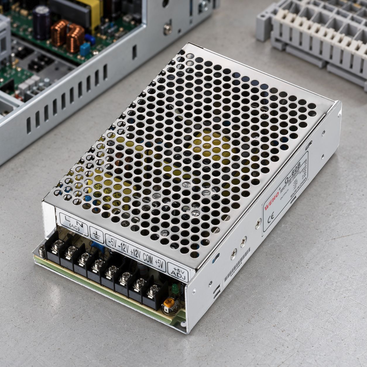
A quad-output switching power supply should be evaluated against the combination of rail loads that the equipment will actually use. Four correct no-load voltages and a plausible total wattage do not establish that every operating state will remain inside its permitted voltage and current limits.
On this page
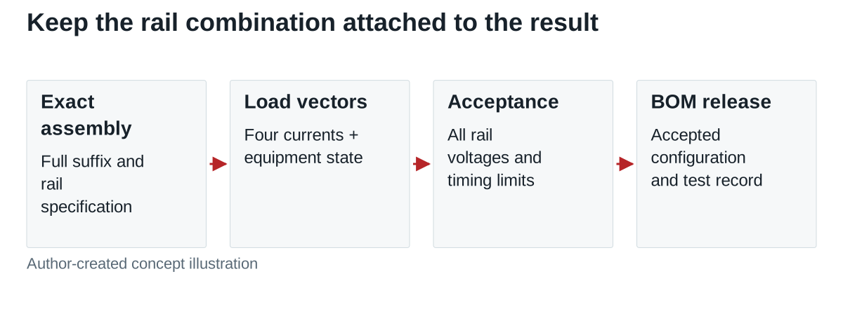
This guide helps an OEM decide whether one multi-output assembly can serve a four-rail load set. Its useful output is a simultaneous-load acceptance matrix attached to the exact supply, load configuration and document revision.
Identify the four-rail assembly
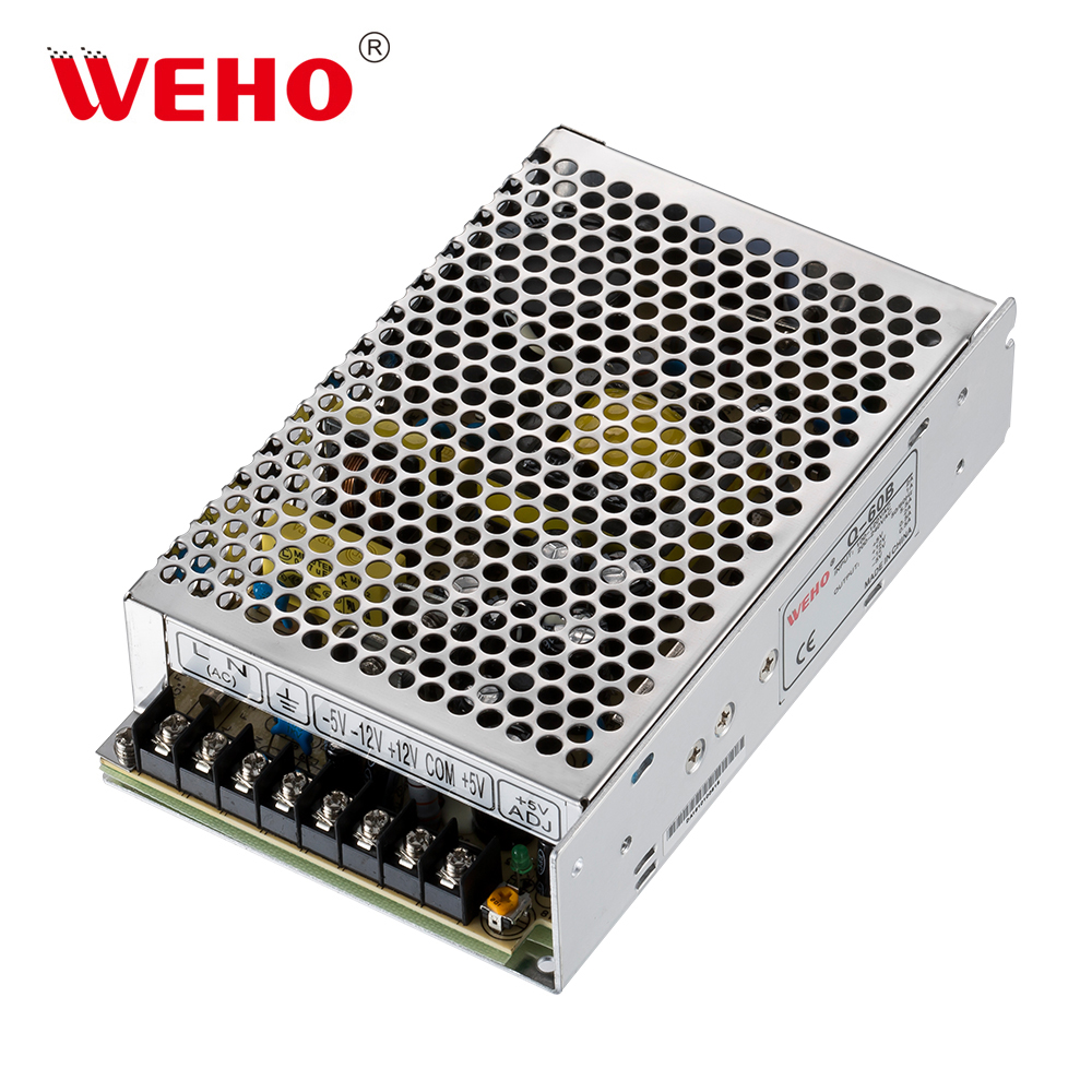
The WEHO Q-60 quad-output supply page is the specific product entry for the Q-60B specimen shown here. Freeze the full suffix and applicable rail table before comparing it with alternatives. A family wattage or a four-output description does not provide the permitted current on each rail, combined limits, minimum loads or start-up sequence.
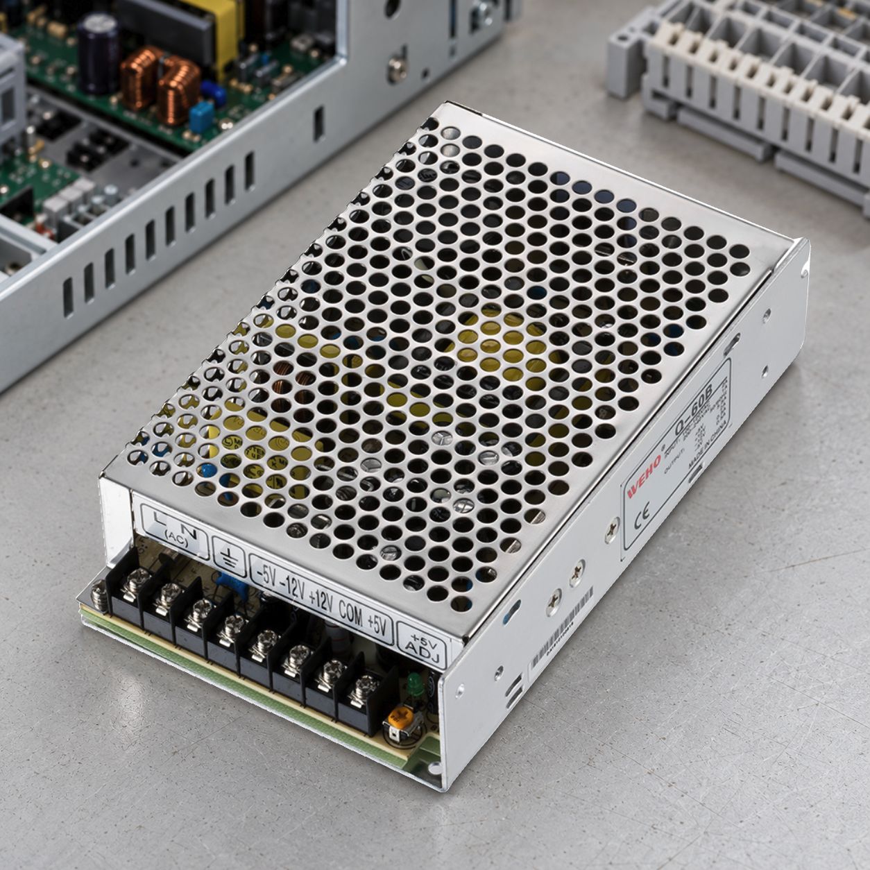
Record the output reference pairs from the controlled terminal drawing separately. That establishes what is connected. The next task is different: demonstrate that the connected equipment’s load combinations are acceptable. Do not interpret several terminal screws as independently regulated or mutually isolated output channels.
Write a load vector for every equipment state
Name the rails and list their minimum, normal, peak and off-state demand. Keep the four currents together as a vector, for example [I1, I2, I3, I4], with the equipment state and timing attached. This preserves combinations that disappear in a single “total watts” figure.
For a calculation example unrelated to Q-60B ratings, assume rails of +5 V, +12 V, −5 V and −12 V supplying current magnitudes of 3.0 A, 1.0 A, 0.10 A and 0.20 A. Their delivered power is 5 × 3.0 + 12 × 1.0 + 5 × 0.10 + 12 × 0.20 = 29.9 W. Use voltage and load-current magnitudes for this delivered-power budget; a negative rail does not subtract its consumed power.
That result is only a total. It does not prove that a nominal 60 W supply permits the 3.0 A rail demand or that the stated load vector meets its coupled conditions. Compare every individual rail limit and every combined restriction before treating the total-power comparison as meaningful.
Select the asymmetric cases
One heavily loaded output and several lightly loaded outputs can be a more revealing condition than evenly loading all outputs. Multi-output converter designs can exhibit cross-regulation: changing the demand on one output affects voltage on another. TI’s SNVA562 application paper explains the mechanism for multi-output flyback converters. It is background for a test question, not evidence of Q-60B’s internal topology or measured regulation.
| State | Load combination to define | Observation |
|---|---|---|
| Standby | Actual low demands, including any off rails | Every receiver voltage and allowed minimum-load condition |
| One subsystem active | One rail high while the others remain light | Loaded-rail droop and other-rail rise or interaction |
| Normal simultaneous operation | Realistic concurrent currents | Per-rail limits, combined power and temperature |
| Subsystem state change | Initial/final current vectors and timing | All affected rail excursions and equipment outcome |
| Power cycle | Defined input-off/on event and connected loads | Rail timing and receiver restart requirements |
For four rails with two chosen load levels each, a complete static binary grid has 2⁴ = 16 combinations. Use engineering judgment to select permitted and relevant cases, then add real dynamic events. A convenient grid should not introduce a prohibited no-load state or replace actual equipment behavior.
Define acceptance at each receiver
Give every observed rail a voltage window, observation point and timing criterion. Measure at the receiver when the harness loss matters, while retaining source-terminal measurements where they help separate supply behavior from distribution effects. Identify bandwidth, probe reference and loading arrangement in the record.
Check the receiver’s permitted power-up and power-down relationships. Four rails starting from one assembly are not automatically simultaneous, sequenced or safe for every mixed-signal circuit. Ask for the applicable model behavior and compare it with the equipment requirement rather than assuming the enclosure supplies the required sequence.
Keep corrections inside the configuration
If a load combination fails, compare an appropriately documented multi-output candidate, a different rail allocation or separate regulated supplies. Any preload or downstream regulator changes the heat, standby demand, startup and component list. Qualify the resulting assembly; do not add a resistor by habit and reuse an earlier acceptance result.
Procurement should receive the exact full model, rail-load matrix, permitted combinations, document revision and accepted sample identity. A substitute with the same four nominal voltages must be reviewed against those records, including state changes and restart, before it enters the production BOM.
Send WEHO your four-rail load and acceptance matrix with input conditions, receiver voltage limits, timing requirements and enclosure environment. Ask for the applicable Q-60B rail specification and a candidate review against your actual simultaneous loads.